Download
1 / 24
240 likes | 244 Views
free manual download

E N D
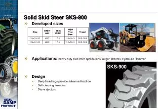
Service Repair Manual Models Caterpillar Cat236 SKID STEER LOADER
236, 246, 248 Skid Steer Loader 4YZ00001-03999 (MACHINE) POWERED BY 3034... 1/5 Shutdown SIS Previous Screen Product: SKID STEER LOADER Model: 236 SKID STEER LOADER 4YZ Configuration: 236, 246, 248 Skid Steer Loader 4YZ00001-03999 (MACHINE) POWERED BY 3034 Engine Disassembly and Assembly 3034 Engine for Caterpillar Built Machines Media Number -SENR5013-08 Publication Date -01/11/2008 Date Updated -14/11/2008 i01368091 Idler Gear - Remove and Install SMCS - 1206 Removal Procedure Start By: A. Remove the fan. Refer to Disassembly and Assembly, "Fan - Remove and Install". B. Remove the front cover. Refer to Disassembly and Assembly, "Housing (Front) - Remove". NOTICE Keep all parts clean from contaminants. Contaminants may cause rapid wear and shortened component life. NOTICE Care must be taken to ensure that fluids are contained during performance of inspection, maintenance, testing, adjusting and repair of the product. Be prepared to collect the fluid with suitable containers before opening any compartment or disassembling any component containing fluids. Refer to Special Publication, NENG2500, "Caterpillar Tools and Shop Products Guide" for tools and supplies suitable to collect and contain fluids on Caterpillar products. Dispose of all fluids according to local regulations and mandates. https://127.0.0.1/sisweb/sisweb/techdoc/techdoc_print_page.jsp?returnurl=/sis... 2019/10/21
236, 246, 248 Skid Steer Loader 4YZ00001-03999 (MACHINE) POWERED BY 3034... 2/5 Illustration 1 g00721939 Note: Rotate the crankshaft until the timing marks on the following gears are aligned: crankshaft gear, camshaft gear, fuel injection pump gear and idler gear (1) . 1. Remove outer washer (3) from the idler gear shaft. 2. Use a suitable puller to remove idler gear (2) . Note: Do not rotate the crankshaft once the idler gear has been removed. If the crankshaft is rotated, the number 1 piston must be set to the top center position. Refer to Testing and Adjusting, "Finding Top Center Position for No. 1 Piston". 3. Remove the inner washer from the idler gear shaft (not shown). The inner washer is located behind the idler gear. Remove the Idler Gear Shaft Table 1 Required Tools Tool Part Number Part Description Qty A 1P-0074 Slide Hammer Puller Gp 1 B 4C-5651 Threaded Adapter 1 https://127.0.0.1/sisweb/sisweb/techdoc/techdoc_print_page.jsp?returnurl=/sis... 2019/10/21
236, 246, 248 Skid Steer Loader 4YZ00001-03999 (MACHINE) POWERED BY 3034... 3/5 Illustration 2 g00721895 (4) Idler gear shaft (5) Oil hole (6) O-ring seal Illustration 3 g00721904 1. Remove O-ring seal (6) . 2. Thread tool (B) onto tool (A) . 3. Use tool (A) to remove idler gear shaft (4) . Install the Idler Gear Shaft Table 2 Required Tools Tool Part Number Part Description Qty C Installation Tool 1 https://127.0.0.1/sisweb/sisweb/techdoc/techdoc_print_page.jsp?returnurl=/sis... 2019/10/21
236, 246, 248 Skid Steer Loader 4YZ00001-03999 (MACHINE) POWERED BY 3034... 4/5 D 159-9076 Seal Installer Handle 1 Illustration 4 g00721922 1. Ensure that oil hole (5) is in the up position. 2. Use a soft hammer (8) to start the idler gear shaft into the cylinder block. Illustration 5 g00721925 3. Use tool (C) and tool (D) to install the idler gear shaft. 4. Drive the idler gear shaft with the installation tool until the installation tool makes contact with the machined surface of the cylinder block. Installation Procedure 1. Install O-ring seal (6) . 2. Install the inner washer onto the idler gear shaft. 3. Install idler gear (2) . https://127.0.0.1/sisweb/sisweb/techdoc/techdoc_print_page.jsp?returnurl=/sis... 2019/10/21
236, 246, 248 Skid Steer Loader 4YZ00001-03999 (MACHINE) POWERED BY 3034... 5/5 Note: Ensure that the timing marks on the crankshaft gear, the camshaft gear, and the fuel injection pump gear are aligned with the timing marks on the idler gear (1) . 4. Install the outer washer (3) onto the idler gear shaft. End By: a. Install the front cover. Refer to Disassembly and Assembly, "Housing (Front) - Install". b. Install the fan. Refer to Disassembly and Assembly, "Fan - Remove and Install". Copyright 1993 - 2019 Caterpillar Inc. Mon Oct 21 22:35:31 UTC+0800 2019 All Rights Reserved. Private Network For SIS Licensees. https://127.0.0.1/sisweb/sisweb/techdoc/techdoc_print_page.jsp?returnurl=/sis... 2019/10/21
236, 246, 248 Skid Steer Loader 4YZ00001-03999 (MACHINE) POWERED BY 3034... 1/3 Shutdown SIS Previous Screen Product: SKID STEER LOADER Model: 236 SKID STEER LOADER 4YZ Configuration: 236, 246, 248 Skid Steer Loader 4YZ00001-03999 (MACHINE) POWERED BY 3034 Engine Disassembly and Assembly 3034 Engine for Caterpillar Built Machines Media Number -SENR5013-08 Publication Date -01/11/2008 Date Updated -14/11/2008 i01354640 Housing (Front) - Remove SMCS - 1151-011 Removal Procedure Start By: A. Remove the alternator. Refer to Disassembly and Assembly, "Alternator - Remove and Install". B. Remove the crankshaft pulley. Refer to Disassembly and Assembly, "Crankshaft Pulley - Remove and Install". C. Remove the fuel injection pump. Refer to Disassembly and Assembly, "Fuel Injection Pump - Remove". NOTICE Keep all parts clean from contaminants. Contaminants may cause rapid wear and shortened component life. NOTICE Care must be taken to ensure that fluids are contained during performance of inspection, maintenance, testing, adjusting and repair of the product. Be prepared to collect the fluid with suitable containers before opening any compartment or disassembling any component containing fluids. https://127.0.0.1/sisweb/sisweb/techdoc/techdoc_print_page.jsp?returnurl=/sis... 2019/10/21
236, 246, 248 Skid Steer Loader 4YZ00001-03999 (MACHINE) POWERED BY 3034... 2/3 Refer to Special Publication, NENG2500, "Caterpillar Tools and Shop Products Guide" for tools and supplies suitable to collect and contain fluids on Caterpillar products. Dispose of all fluids according to local regulations and mandates. Illustration 1 g00594914 1. Disconnect return spring (1) from the throttle lever on the front housing. Note: It is necessary to get a reference for the maximum fuel setting in order to remove the front housing. This setting must be taken from the original front housing before the front housing is removed. 2. Establish a reference for the maximum fuel setting. Refer to the Testing and Adjusting Module, "Fuel Setting - Adjust" topic for more information. Illustration 2 g00595216 3. Remove four nuts (3), bolt (2), and plate (4) from the back side of the front housing. https://127.0.0.1/sisweb/sisweb/techdoc/techdoc_print_page.jsp?returnurl=/sis... 2019/10/21
236, 246, 248 Skid Steer Loader 4YZ00001-03999 (MACHINE) POWERED BY 3034... 3/3 Illustration 3 g00598941 4. Remove bolts (5) from the back side of the front housing. Illustration 4 g00598948 Note: Mark the location of the bolts for the front housing. The bolts for the front housing are different lengths and the bolts must be installed in the original location. 5. Remove bolts (6) and two nuts (7) that fasten the front housing to the cylinder block. 6. Remove front housing (8) and the gasket from the cylinder block. Inspect the gasket and the front housing for damage. If the gasket or the front housing is damaged, use new parts for replacement. Copyright 1993 - 2019 Caterpillar Inc. Mon Oct 21 22:36:30 UTC+0800 2019 All Rights Reserved. Private Network For SIS Licensees. https://127.0.0.1/sisweb/sisweb/techdoc/techdoc_print_page.jsp?returnurl=/sis... 2019/10/21
236, 246, 248 Skid Steer Loader 4YZ00001-03999 (MACHINE) POWERED BY 3034... 1/3 Shutdown SIS Previous Screen Product: SKID STEER LOADER Model: 236 SKID STEER LOADER 4YZ Configuration: 236, 246, 248 Skid Steer Loader 4YZ00001-03999 (MACHINE) POWERED BY 3034 Engine Disassembly and Assembly 3034 Engine for Caterpillar Built Machines Media Number -SENR5013-08 Publication Date -01/11/2008 Date Updated -14/11/2008 i01354651 Housing (Front) - Install SMCS - 1151-012 Installation Procedure NOTICE Keep all parts clean from contaminants. Contaminants may cause rapid wear and shortened component life. 1. Make sure that the mating surfaces of the front housing and the cylinder block are clean and free from damage. Illustration 1 g00598948 https://127.0.0.1/sisweb/sisweb/techdoc/techdoc_print_page.jsp?returnurl=/sis... 2019/10/21
236, 246, 248 Skid Steer Loader 4YZ00001-03999 (MACHINE) POWERED BY 3034... 2/3 2. Put the gasket and front housing (8) in position on the engine. Note: The bolts for the front housing are different lengths and the bolts must be installed in the original location. 3. Install two nuts (7) and bolts (6) that fasten the front housing to the engine. Illustration 2 g00598941 4. Install bolts (5) in the back side of the front housing. Illustration 3 g00595216 5. Put plate (4) in position on the engine and install bolt (2) and four nuts (3) . 6. Set the maximum fuel adjustment. Refer to the Testing and Adjusting Module, "Fuel Setting - Adjust" topic for more information. https://127.0.0.1/sisweb/sisweb/techdoc/techdoc_print_page.jsp?returnurl=/sis... 2019/10/21
236, 246, 248 Skid Steer Loader 4YZ00001-03999 (MACHINE) POWERED BY 3034... 3/3 Illustration 4 g00594914 7. Connect return spring (1) to the throttle lever on the front housing. End By: a. Install the fuel injection pump. Refer to Disassembly and Assembly, "Fuel Injection Pump - Install". b. Install the crankshaft pulley. Refer to Disassembly and Assembly, "Crankshaft Pulley - Remove and Install". c. Install the alternator. Refer to Disassembly and Assembly, "Alternator - Remove and Install". Copyright 1993 - 2019 Caterpillar Inc. Mon Oct 21 22:37:29 UTC+0800 2019 All Rights Reserved. Private Network For SIS Licensees. https://127.0.0.1/sisweb/sisweb/techdoc/techdoc_print_page.jsp?returnurl=/sis... 2019/10/21
236, 246, 248 Skid Steer Loader 4YZ00001-03999 (MACHINE) POWERED BY 3034... 1/3 Shutdown SIS Previous Screen Product: SKID STEER LOADER Model: 236 SKID STEER LOADER 4YZ Configuration: 236, 246, 248 Skid Steer Loader 4YZ00001-03999 (MACHINE) POWERED BY 3034 Engine Disassembly and Assembly 3034 Engine for Caterpillar Built Machines Media Number -SENR5013-08 Publication Date -01/11/2008 Date Updated -14/11/2008 i01150784 Crankcase Breather - Remove and Install SMCS - 1317-010 Removal Procedure NOTICE Keep all parts clean from contaminants. Contaminants may cause rapid wear and shortened component life. NOTICE Care must be taken to ensure that fluids are contained during performance of inspection, maintenance, testing, adjusting and repair of the product. Be prepared to collect the fluid with suitable containers before opening any compartment or disassembling any component containing fluids. Refer to Special Publication, NENG2500, "Caterpillar Tools and Shop Products Guide" for tools and supplies suitable to collect and contain fluids on Caterpillar products. Dispose of all fluids according to local regulations and mandates. https://127.0.0.1/sisweb/sisweb/techdoc/techdoc_print_page.jsp?returnurl=/sis... 2019/10/21
236, 246, 248 Skid Steer Loader 4YZ00001-03999 (MACHINE) POWERED BY 3034... 2/3 Illustration 1 g00610373 1. Loosen bolts (3) and remove breather cover (6) from the valve mechanism cover. 2. Remove the diaphragm and plate (4). Remove spring (5) . 3. Clean vent hole (2) and breather tube (1). Clean cavity (7) for the breather assembly in the valve mechanism cover. Installation Procedure NOTICE Keep all parts clean from contaminants. Contaminants may cause rapid wear and shortened component life. NOTICE Make sure that the components of the breather assembly are installed correctly. Engine damage may occur if the breather assembly is not working properly. https://127.0.0.1/sisweb/sisweb/techdoc/techdoc_print_page.jsp?returnurl=/sis... 2019/10/21
236, 246, 248 Skid Steer Loader 4YZ00001-03999 (MACHINE) POWERED BY 3034... 3/3 Illustration 2 g00610373 1. Install a new spring (5) in cavity (7) for the breather assembly. 2. Install a new diaphragm and plate (4) on top of spring (5) . 3. Install breather cover (6) and four bolts (3). Tighten the bolts to a torque of 9 N·m (80 lb in). Copyright 1993 - 2019 Caterpillar Inc. Mon Oct 21 22:38:28 UTC+0800 2019 All Rights Reserved. Private Network For SIS Licensees. https://127.0.0.1/sisweb/sisweb/techdoc/techdoc_print_page.jsp?returnurl=/sis... 2019/10/21
236, 246, 248 Skid Steer Loader 4YZ00001-03999 (MACHINE) POWERED BY 3034... 1/3 Shutdown SIS Previous Screen Product: SKID STEER LOADER Model: 236 SKID STEER LOADER 4YZ Configuration: 236, 246, 248 Skid Steer Loader 4YZ00001-03999 (MACHINE) POWERED BY 3034 Engine Disassembly and Assembly 3034 Engine for Caterpillar Built Machines Media Number -SENR5013-08 Publication Date -01/11/2008 Date Updated -14/11/2008 i01317371 Valve Mechanism Cover - Remove and Install SMCS - 1107-010 Removal Procedure NOTICE Keep all parts clean from contaminants. Contaminants may cause rapid wear and shortened component life. NOTICE Care must be taken to ensure that fluids are contained during performance of inspection, maintenance, testing, adjusting and repair of the product. Be prepared to collect the fluid with suitable containers before opening any compartment or disassembling any component containing fluids. Refer to Special Publication, NENG2500, "Caterpillar Tools and Shop Products Guide" for tools and supplies suitable to collect and contain fluids on Caterpillar products. Dispose of all fluids according to local regulations and mandates. https://127.0.0.1/sisweb/sisweb/techdoc/techdoc_print_page.jsp?returnurl=/sis... 2019/10/21
236, 246, 248 Skid Steer Loader 4YZ00001-03999 (MACHINE) POWERED BY 3034... 2/3 Illustration 1 g00583098 1. Loosen hose clamps (1) and remove breather tube (2) from the engine. Illustration 2 g00583101 2. Remove three cap nuts (3), the washers and the rubber seals. 3. Remove valve mechanism cover (4) and the gasket from the engine. Installation Procedure NOTICE Keep all parts clean from contaminants. Contaminants may cause rapid wear and shortened component life. 1. Check the condition of the gasket and the rubber seals. If the gasket or the rubber seals are worn or damaged, use new parts for replacement. https://127.0.0.1/sisweb/sisweb/techdoc/techdoc_print_page.jsp?returnurl=/sis... 2019/10/21
236, 246, 248 Skid Steer Loader 4YZ00001-03999 (MACHINE) POWERED BY 3034... 3/3 Illustration 3 g00583101 2. Put the gasket and valve mechanism cover (4) in position on the engine. 3. Lubricate cap nuts (3) with clean engine oil. Install the rubber seals, the washers and cap nuts (3) . Note: Do not overtighten the cap nuts on the valve mechanism cover. 4. Tighten cap nuts (3) to a torque of 11 N·m (8 lb ft). Illustration 4 g00583098 5. Put breather tube (2) in position on the engine and tighten hose clamps (1) . Copyright 1993 - 2019 Caterpillar Inc. Mon Oct 21 22:39:28 UTC+0800 2019 All Rights Reserved. Private Network For SIS Licensees. https://127.0.0.1/sisweb/sisweb/techdoc/techdoc_print_page.jsp?returnurl=/sis... 2019/10/21
Thank you very much for your reading. Please Click Here. Then Get COMPLETE MANUAL. NO WAITING NOTE: If there is no response to click on the link above, please download the PDF document first and then click on it.
236, 246, 248 Skid Steer Loader 4YZ00001-03999 (MACHINE) POWERED BY 3034... 1/3 Shutdown SIS Previous Screen Product: SKID STEER LOADER Model: 236 SKID STEER LOADER 4YZ Configuration: 236, 246, 248 Skid Steer Loader 4YZ00001-03999 (MACHINE) POWERED BY 3034 Engine Disassembly and Assembly 3034 Engine for Caterpillar Built Machines Media Number -SENR5013-08 Publication Date -01/11/2008 Date Updated -14/11/2008 i01318486 Rocker Shaft and Pushrod - Remove SMCS - 1102-011; 1208-011 Removal Procedure Start By: A. Remove the valve mechanism cover. Refer to Disassembly and Assembly, "Valve Mechanism Cover - Remove and Install". NOTICE Keep all parts clean from contaminants. Contaminants may cause rapid wear and shortened component life. NOTICE Care must be taken to ensure that fluids are contained during performance of inspection, maintenance, testing, adjusting and repair of the product. Be prepared to collect the fluid with suitable containers before opening any compartment or disassembling any component containing fluids. Refer to Special Publication, NENG2500, "Caterpillar Tools and Shop Products Guide" for tools and supplies suitable to collect and contain fluids on Caterpillar products. Dispose of all fluids according to local regulations and mandates. https://127.0.0.1/sisweb/sisweb/techdoc/techdoc_print_page.jsp?returnurl=/sis... 2019/10/21
236, 246, 248 Skid Steer Loader 4YZ00001-03999 (MACHINE) POWERED BY 3034... 2/3 Illustration 1 g00698000 1. Loosen eight bolts (1) that fasten the brackets for the rocker shaft (4) to the cylinder head. Begin with the inner bolts and work toward the outer bolts. 2. Loosen four nuts (3). Begin with the inner nuts and work toward the outer nuts. Note: Rocker shaft brackets (4) contain three plates (2) that include the studs for the valve mechanism cover. The plates must be installed in the original location in order to install the valve mechanism cover. 3. Remove bolts (1) and nuts (3) from the brackets for the rocker shaft (4) . https://127.0.0.1/sisweb/sisweb/techdoc/techdoc_print_page.jsp?returnurl=/sis... 2019/10/21
236, 246, 248 Skid Steer Loader 4YZ00001-03999 (MACHINE) POWERED BY 3034... 3/3 Illustration 2 g00590103 4. Remove rocker shaft assembly (4) from the cylinder head. Note: Roll pins (5) are installed in the brackets of rocker shaft (4) in order to align rocker shaft assembly (4) with oil holes (7) in the cylinder head. Oil holes (7) provide lubrication to rocker shaft assembly (4) . 5. Place an identification mark on each pushrod (6) in order to locate the pushrods for installation. Remove eight pushrods (6) from the engine. Copyright 1993 - 2019 Caterpillar Inc. Mon Oct 21 22:40:27 UTC+0800 2019 All Rights Reserved. Private Network For SIS Licensees. https://127.0.0.1/sisweb/sisweb/techdoc/techdoc_print_page.jsp?returnurl=/sis... 2019/10/21
236, 246, 248 Skid Steer Loader 4YZ00001-03999 (MACHINE) POWERED BY 3034... 1/3 Shutdown SIS Previous Screen Product: SKID STEER LOADER Model: 236 SKID STEER LOADER 4YZ Configuration: 236, 246, 248 Skid Steer Loader 4YZ00001-03999 (MACHINE) POWERED BY 3034 Engine Disassembly and Assembly 3034 Engine for Caterpillar Built Machines Media Number -SENR5013-08 Publication Date -01/11/2008 Date Updated -14/11/2008 i01511617 Rocker Shaft - Disassemble SMCS - 1102-015 Disassembly Procedure Start By: A. Remove the rocker shaft assembly. Refer to Disassembly and Assembly, "Rocker Shaft and Pushrod - Remove". NOTICE Keep all parts clean from contaminants. Contaminants may cause rapid wear and shortened component life. NOTICE Care must be taken to ensure that fluids are contained during performance of inspection, maintenance, testing, adjusting and repair of the product. Be prepared to collect the fluid with suitable containers before opening any compartment or disassembling any component containing fluids. Refer to Special Publication, NENG2500, "Caterpillar Tools and Shop Products Guide" for tools and supplies suitable to collect and contain fluids on Caterpillar products. Dispose of all fluids according to local regulations and mandates. https://127.0.0.1/sisweb/sisweb/techdoc/techdoc_print_page.jsp?returnurl=/sis... 2019/10/21
236, 246, 248 Skid Steer Loader 4YZ00001-03999 (MACHINE) POWERED BY 3034... 2/3 Illustration 1 g00705531 1. Use a screwdriver or a similar tool to remove retaining ring (6) from both ends of the rocker shaft assembly. 2. Remove rocker lever (5) from the rocker shaft. 3. Remove rocker shaft bracket (4) from the rocker shaft. 4. Remove spacer (3) and spring (2) from the rocker shaft (1) . Note: Place an identification mark on each of the components for installation. Note: The rocker shaft bracket (4) on newer engines is a split assembly. Mon Oct 21 22:41:26 UTC+0800 2019 https://127.0.0.1/sisweb/sisweb/techdoc/techdoc_print_page.jsp?returnurl=/sis... 2019/10/21