Download

1 / 60
610 likes | 845 Views
Wafer Cut and Rotation to Improve the Compound yield for 3D Wafer-on-Wafer Stacking Bei Zhang. Thesis Advisor: Dr . Vishwani D. Agrawal Thesis Committee : Dr. Victor Nelson Dr . Adit Singh Dr. Charles Stroud. Department of Electrical and Computer Engineering

E N D
Wafer Cut and Rotation to Improve the Compound yield for 3D Wafer-on-Wafer Stacking Bei Zhang • Thesis Advisor:Dr. Vishwani D. Agrawal • Thesis Committee: Dr. Victor Nelson • Dr. Adit Singh • Dr. Charles Stroud Department of Electrical and Computer Engineering Auburn University, AL 36849 USA
Presentation Outline • Introduction • Problem Statement • Previous efforts • Our efforts • Proposed a hybrid wafer stacking procedure • Proposed a new wafer manipulation method • Exploited more defect models • Die per sector calculator • Experimental results • Future work • Pollution elimination • Find the optimal number of cuts • Conclusion Bei’s General exam
Introduction • What’s 3D IC? • A chip in which two or more layers of active electronic components are integrated horizontally or verticallyinto • a single circuit. Wikipedia: http://en.wikipedia.org/wiki/Three-dimensional_integrated_circuit Bei’s General exam
Introduction • 3D IC basic structure: • Through silicon • Via (TSV) Bei’s General exam
Introduction • 3D Packaging? • 3D transistor? • In 3D packaging, separate chips are stacked in a single package. However, these chips are not integrated into a single circuit. Bei’s General exam
Introduction • Why 3D IC? • TSV connect the planar wafer in the vertical direction. • This reduces the need for long wires which in turn • reduces the delay and power consumption. • Heterogeneous integration. • Reduced foot-print size,desirable in hand-held devices. Bei’s General exam
Introduction • 3D IC fabrication methods: • Die on Die stacking (D2D) • Die on Wafer stacking (D2W) • Advantages : Higher yield, can stack only known good dies • Disadvantages: 1) Hard to handle and stack, Process expensive • 2) Low throughput • 3) May not applicable to high-end systems • Wafer on Wafer stacking (W2W) • Advantages : 1) Highest throughput • 2) Allows for highest TSV density • Disadvantages: Low compound stacking yield Bei’s General exam
Introduction • Why compound yield loss in W2W stacking? Bei’s General exam
Introduction • Wafers versus Layers in 3D W2W stacking M. Taouil, S. Hamdioui, J. Verbree, and E. Marinissen, “On Maximizing the compound yield for 3D wafer-to-wafer stacked IC," in Proc. International Test Conf., 2010, pp. 1-10. Bei’s General exam
Presentation Outline • Introduction • Problem Statement • Previous efforts • Our efforts • Proposed a hybrid wafer stacking procedure • Proposed a new wafer manipulation method • Exploited more defect models • Die per sector calculator • Experimental results • Future work • Pollution elimination • Find the optimal number of cuts • Conclusion Bei’s General exam
Problem Statement • Conditions: • N number of repositories each with K wafers • Fault maps for all wafers based on pre-bond testing • A production size of M 3D ICs • Objective: • Maximize the overall compound yield • OR • Maximize the overall number of good 3D ICs Bei’s General exam
Presentation Outline • Introduction • Problem Statement • Previous efforts • Our efforts • Proposed a hybrid wafer stacking procedure • Proposed a new wafer manipulation method • Exploited more defect models • Die per sector calculator • Experimental results • Future work • Pollution elimination • Find the optimal number of cuts • Conclusion Bei’s General exam
Previous Efforts • Exploiting different repository replenishment schemes • Exploiting various matching algorithms • Exploiting different matching criteria • Exploiting more practical defect models • Specifically design wafers for matching Bei’s General exam
Different Repository Schemes • Repository replenish schemes can be: • Static Repository • None of the repositories will be replenished until • they run out of wafers. • Running Repository • Each repository is immediately replenished with a new wafer each time a wafer is selected. M. Taouil, S. Hamdioui, J. Verbree, and E. J. Marinissen, “On Maximizing the compound yield for 3D wafer-to-wafer stacked IC," in Proc. International Test Conf., 2010, pp. 1-10. Bei’s General exam
Matching Algorithms • Matching algorithms based on Static repository: • Globally greedy matching • Iterative matching heuristic • Integer linear programming • Iterative greedy S. Reda, G. Smith, and L. Smith, “Maximizing the Functional Yield of Wafer-to-Wafer 3-D Integration,” IEEE Transactions on Very Large Scale Integration (VLSI) Systems, vol. 17, no. 9, pp. 1357–1362, Sept. 2009.
Matching Algorithms • Matching algorithms based on Running repository: • First in First out 1 (FIFO1) • First in First out n (FIFOn) • Best Pair (BP) A general W2W matching framework can be found in Taouil’s ITC paper, 2010
Matching Criteria • Matching criteria: • Maximize matching good dies • Maximizing matching bad dies • Minimize matching between good and bad dies (UF)
More Practical WaferMaps • Illustration of two different kinds of wafer maps: Clustered Uniform
SpecificallyDesigned Wafers • Wafers fabricated with rotational symmetry: Double rotation Fourfold rotation B. Zhang, B. Li, V. D. Agrawal, “Wafer cut and rotation to improve the compound yield for 3D Wafer-on-Wafer stacking,“ Proc. International Test Conf., 2013, submitted. E. Singh, “Exploiting Rtational Symmetries for Improved Stacked Yields in W2W 3D-SICs,” in Proc. IEEE 29th VLSI Test Symposium (VTS), 2011, pp. 32–37.
Presentation Outline • Introduction • Problem Statement • Previous efforts • Our efforts • Proposed a hybrid wafer stacking procedure • Proposed a new wafer manipulation method • Exploited more defect models • Die per sector calculator • Experimental results • Future work • Pollution elimination • Find the optimal number of cuts • Conclusion Bei’s General exam
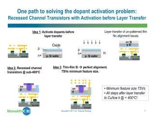
Illustration of Our Efforts • A hybrid stacking procedure and a new wafer manipulation method: B. Zhang, B. Li, V. D. Agrawal, “Wafer cut and rotation to improve the compound yield for 3D Wafer-on-Wafer stacking,“ Proc. International Test Conf., 2013, submitted.
Wafer Cut and Rotation • Common wafer cut into sectors Bei’s General exam
Wafer Cut and Rotation • Cut rotationally symmetric wafer to sectors: Bei’s General exam
Wafer Cut and Rotation • Sub-wafers rotation: Bei’s General exam
Wafer Cut and Rotation • Discussion on the number of cuts: • Illustration of Die loss on a wafer Places where no die can be placed Bei’s General exam
Process Flow Bei’s General exam
Summary • Different wafer manipulation methods: Bei’s General exam
Presentation Outline • Introduction • Problem Statement • Previous efforts • Our efforts • Proposed a hybrid wafer stacking procedure • Proposed a new wafer manipulation method • Exploited more defect models • Die per sector calculator • Experimental results • Future work • Pollution elimination • Find the optimal number of cuts • Conclusion Bei’s General exam
Experiments • Experiment setup: • We consider 200-mm wafers with • edge clearance set as 5 mm. • Three types of chips with different die sizes: • Type1: 31.8 mm2, dies per wafer is 804, overall yield is 80.04%, • Type2: 63.4 mm2, dies per wafer is 436, overall yield is 61.27% • Type3: 131.6 mm2, dies per wafer is 184, overall yield is 50.97%
Experiments • Experiment setup: • A production size of 100,000 3D ICs is targeted in • all experiments for each type of chips. • The running repository based best-pair matching algorithm • is utilized in the experiment. • Employ Heap structure to speed up the matching process Bei’s General exam
Defect Model Used • 1) Uniform defect model • 2) Radial clustered degradation model: Inner core yield Type1: 88% Type2: 80% Type3: 70% D. Teets, “A Model for Radial Yield Degradation as a Function of Chip Size,” IEEE Transactions on Semiconductor Manufacturing, vol. 9, no. 3, pp. 467–471, 1996. Normalized yield versus radius for three types of chips
Comparison of Stacking Procedures on Uniformand ClusteredDefectModels • Number of stacked layers: 2 Yield comparison between Basic, Rotation2, CR2 for type 3 chip
Impact of Cut Number and Rotation Number on Compound Yield • Number of stacked layers: 3 Normalized yield versus repository size for type 3 chips
Impact of Total Number of Stacked Layers on Compound Yield • Repository size is set as 50 Normalized yield versus number of stacked layers for type 3 chip
Impact of Wafer Yield on Compound Yield • Repository size is set as 50 Normalized yield versus inner core wafer yield for type 3 chip
Impact of Production Sizeon Compound Yield • Repository size : 25 Normalized yield versus production size for type 3 chip
Exploit More DefectModels G. DeNicoao, E. Pasquinetti, G. Miraglia, and F. Piccinini, “Unsupervised spatial pattern classification of electrical fail-ures in semiconductor manufacturing,” in Artif. Neural Net-works Pattern Recognit. Workshop, 2003, pp. 125–131. The spatial probability functions used to generate the simulated Wafers. Gray levels correspond to failure probabilities ranging from 0 (white) to 1 (black)
Yield Comparison BetweenDifferentStacking Procedures (a) Pattern 1 (b) Pattern 2 (c) Pattern 3 (d) Pattern 4 (e) Pattern 5 (f) Pattern 6 (g) Pattern 7 (h) Pattern 8 (i) Pattern 9
Impact of Number of Stacked Layerson Compound Yield (a) Pattern 1 (b) Pattern 2 (c) Pattern 3 (d) Pattern 4 (e) Pattern 5 (f) Pattern 6 39 (g) Pattern 7 (h) Pattern 8 (i) Pattern 9
Impact of Production Sizeon Compound Yield (a) Pattern 1 (b) Pattern 2 (c) Pattern 3 (d) Pattern 4 (e) Pattern 5 (f) Pattern 6 40 (g) Pattern 7 (h) Pattern 8 (i) Pattern 9
Presentation Outline • Introduction • Problem Statement • Previous efforts • Our efforts • Proposed a hybrid wafer stacking procedure • Proposed a new wafer manipulation method • Exploited more defect models • Die per sector calculator • Experimental results • Future work • Pollution elimination • Find the optimal number of cuts • Conclusion Bei’s General exam
Repository Pollution (downside of running repository) • Phenomenon: • As the production size increases (large production volume), the compound yield of 3D stacked IC decreases continuously. • Reasons: • Unattractive wafers remain in the repository for many iterations, • occupying space, and in effect reducing the size of the repository • in the long run. • General solution: • Need a mechanism to force the unattractive wafers to leave the repository in a timely manner. M. Taouil, S. Hamdioui, J. Verbree, and E. J. Marinissen, “On Maximizing the compound yield for 3D wafer-to-wafer stacked IC," in Proc. International Test Conf., 2010, pp. 1-10. Bei’s General exam
Repository Pollution (downside of running repository) • Possible detailed solutions: • Conduct running repository based matching and static repository • based matching, alternatively. • Expunge poor wafers/quadrants from the repository if they • have not been used after n tries, send them to a die stacking • process to make some use of them • Exploiting a mechanism to force the unattractive wafer leave • the repository at the same rate as they come in. • Utilize partial repository instead of running repository to reduce • pollution and also enhance the compound yield. Bei’s General exam
Find OptimalNumber of Cuts (Current research is exploring this aspect) • In case of more than 4 cuts, two methods of placement: Placement method 1 Placement method 2 Bei’s General exam
# of Dies Per Sector (DPS) Calculator • Placement method 1: Bei’s General exam
# of Dies PerSector(DPS) Calculator • Placement method 2: Bei’s General exam
Relationship Between DPW and # of Cuts --- Case Study • # of Type 1 dies per wafer: DPW V.S. number of cuts for placement method 1 and 2
Relationship Between DPW and # of Cuts --- Case Study • # of Type 2 dies per wafer: DPW V.S. number of cuts for placement method 1 and 2
Relationship Between DPW and # of Cuts --- Case Study • # of Type 3 dies per wafer: DPW V.S. number of cuts for placement method 1 and 2
Typical Die Size http://www.geek.com/glossary/die-size/ Bei’s General exam