Download
1 / 15
150 likes | 255 Views
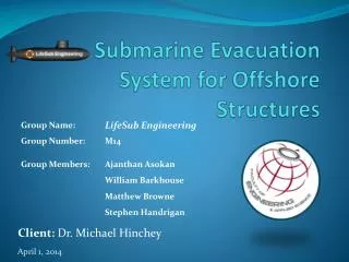
Submarine Evacuation System for Offshore Structures. Client: Dr. Michael Hinchey. Agenda. Project Overview Prototype Design Evolution Structural Material Control Analysis Lifting Finite Element Analysis (FEA) Motion (Flow3D) Control Codes & Sequence Testing Methods

E N D
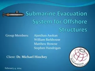
Submarine Evacuation System for Offshore Structures Client: Dr. Michael Hinchey
Agenda • Project Overview • Prototype Design Evolution • Structural • Material • Control • Analysis • Lifting • Finite Element Analysis (FEA) • Motion (Flow3D) • Control Codes & Sequence • Testing Methods • Deployment Strategies • Moving Forward • Questions
Project Overview • Current Problem • Lifeboats – Exposed to Hazards • Freefall – Uncontrolled • Proposed Solution • Deployable Submarine • Project Goals • Develop and Test Automated Submarine Prototype • Develop and Test Deployment Options • Identify Design Requirements • Prove Operational Viability • Make Recommendations on Full-scale Development
Prototype Design Evolution • Structural • Lifting Hook • Tail Sweep • Propeller Shroud • Material • Previous – 6” OD Aluminum Round Stock • Current • Hull – 6” ID, PVC Pipe • Endcaps – Solid Round Stock ABS • Shroud – RP ABS Phase 1 Phase 2
Prototype Design Evolution • Controls • Experimental Circuit (Breadboard) • Initial code testing • Printed Circuit Board (PCB) • Fine-tuning with prototype equipment • Execute submarine control
Analysis: Lifting • Applied Load: 125 (N) • Maximum Lift Acceleration: 1 (m/s2) • Lifting Hook – ¼” x 20 UNC Nylon • Maximum Stress due to Bending • Lifting Angle Limit: 10° (S.F. 2) • Torque Requirement: 1 (N-m) • End Cap Fasteners - 4 x ¼ x 28 UNC Nylon • Utilization: 2% of Yield Strength • Torque Requirement: 1 (N-m) 10°
Finite Element Analysis (FEA) • Quarter Model Hydrostatic Analysis • Boundary Conditions • Roller Side Boundaries • Fixed at Nose • Setup • Pressure: 60 kPa (~6m) • Mesh: 6mm curvature • Results • Limiting Safety Factor: 11.47 • Max Deflection: 35.2 µm MIN: 11.47 S.F.
Motion Analysis: Flow3D • Conditions • Preset amount of ballast • Fully submerged • Still water • Exclude buoyancy control • Uniform density • Setup • Acceleration: 0.1 m/s2 downwards • Disp. Mass: 11.2 kg; Mass: 11.31 kg • Hollow body with point mass • Result: COG ~10mm below COB 4 ft 5.2 ft 2.8 ft
Control Codes • Speed Control Code • Varying thruster RPM • Depth Control Code • Maintain desired depth band • Roll & Pitch Code • Continual monitoring of roll and pitch • Potentiometer • Replicates sensor • Thruster • Replicates thruster • ± 2.5 V • Stepper Motor • Replicates Pump • Ballast Control
Code Sequence + Φ - Φ + θ - θ Z1 + Z Z2
Testing Methods • Static Commissioning • Water Tight Hull Test • External Ballast System Pressure Test • Dynamic Commissioning • Depth Driven Ballast Test • Rotation Driven Thrust Test • Pitch • Roll • Depth
Deployment Strategies 1. Vertical Deployment • Propeller-down launch • Underwater • Avoid GBS interference 2. Horizontal Launch • Release bay filled with water • Exit from enclosed piping 3. Horizontal Docking • Connect with GBS 2. 1. 3.
Moving Forward • Refine Flow3D Model using an upgraded version of Flow3D • Complete construction and fabrication • Continue optimizing control codes • Perform testing and analysis • Phase 3 Decision: • Develop general recommendations for full-scale implementation
Questions? Thank-you www.lifesubengineering.weebly.com