Download
1 / 44
440 likes | 560 Views
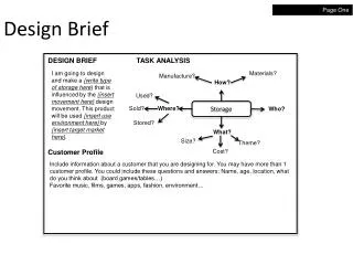
Design Brief. Design and make a pedestrian / cyclist safety light. The safety light must be programmed to flash high brightness LEDs on and off . Research homework: Complete research to enable you to decide what type of product you will design. Areas of investigation should include:

E N D
Design Brief • Design and make a pedestrian / cyclist safety light. • The safety light must be programmed to flash high brightness LEDs on and off. Research homework: Complete research to enable you to decide what type of product you will design. Areas of investigation should include: Research of pedestrian/cycle safety products already on the market that utilise LEDs or that could be developed to utilise LEDs Research of the situation – why would cyclists/pedestrians need a safety light?
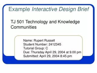
Auto-Bi Kerosene Headlamp The E.R. Thomas Motor Company's "Auto-Bi" or "Auto-Bike" began production in 1901, making E.R. Thomas one of the first manufacturers in the United States to mass-produce motor driven cycles.
Design Specification Points to include: • The design will use a PICAXE-08 microcontroller as it’s controller. • The design will include 3 high brightness LEDs. • The design will be able to optionally react to changes in light levels. Add further points that are of importance to your target market and research
Printed Circuit Board Track Side This side contains the circuit (tracks) that joint the components together Component Side This side is where the components are (usually) mounted
Fixed resistor This fixed resistor has a fixed resistance which is indicated by a colour code.
330 Ω (ohms) 4700 Ω (4.7kΩ) 2 1 ? 47000 Ω (47kΩ) ? 3
Light Emitting Diodes These can be red, green, amber or yellow in colour. They must be connected the right way round. The positive leg of an LED is longer than the negative leg. The negative leg also has a flat edge on the plastic casing of the LED.
Batteries and Battery Box A battery (cell) is a self-contained source of electrical energy. It is a portable power supply. Batteries contain chemicals that store energy. When connected into a circuit this chemical energy is converted to electrical energy that can then power the circuit.
Slider Switch Used to switch the circuit On or Off
Microcontroller Microcontrollers are used as the ‘brain’ in electronic circuits. Microcontrollers are purchased ‘blank’ and then programmed with a specific control program. Once programmed the microcontroller is built into a product to make the product more intelligent and easier to use. Microcontrollers are used in automatically controlled products and devices, such as automobile engine control systems, remote controls, office machines, appliances, power tools, and toys.
IC Socket The IC sockets is soldered to the PCB and The microcontroller is plugged into it. IC sockets provide an advantage over directly attaching microcontrollers to the PCB by making it easier to replace the processor in the event of a failure. The microcontroller is often the most expensive component in the system and the cost of a IC socket is relatively low.
Download Socket The download socket is used to connect the PCB to a computer. The programme created on the computer can then be downloaded to the microcontroller
Light Dependant Resistor - LDR A Light Dependent Resistor (LDR) is special type of resistor that reacts to changes in light level. The resistance of the LDR changes as different amounts of light fall on the top 'window' of the device. This allows electronic circuits to measure changes in light level. LDRs are used in automatic street lamps to switch them on at night and off during the day. They are also used within many alarm and toys to measure light levels.
Safety Light Components • PCB printed circuit board • R1, R2, R3 120R resistor (brown red brown gold) • R4 10k resistor (brown black orange gold) • R5 22k resistor (red red orange gold) • R6 10k resistor (brown black orange gold) • LED1, 2, 3 High brightness LEDs • SW1 On/off slide switch • IC1 8 pin IC socket • IC1 PICAXE-08 microcontroller • CT1 PICAXE download 3.5mm socket • BT1 3V (2xAAA) battery • wire To connect LEDs • LDR Miniature light dependent resistor
Place the three 120 (brown red brown gold) resistors in positions R1, R2 and R3 R1 R2 R3
Place the two 10k (brown black orange gold) resistor in positions R4 & R6. R4 R6
Place the 22k (red red orange gold) resistor in position R5 R5
Push the download socket onto the PCB and make sure it clicks intoposition (so that it lies flat on the board).
Push the IC socket into position. Make sure the notch at one end points towards the resistors. Notch
Place the first LED into position marked LED1Make sure the legs are in the correct positions.
Make sure the bottom of the LED is level with the top ofthe switch i.e. the LED is about 6mm above the PCB. 6 mm
Bend the LED around the edge of the PCB so the LED is now on the track side of the PCB
Connect the wires from the battery case in the position marked BTNote: Black = negative & Red = positive
Cut 4 wires (2 red, 2 black) 100mm long.Solder one red (+ve) and one black (-ve) wire to LED2 & LED3Slide on insulating tubing. Long leg +ve Short leg -ve
Solder the Light Dependant Resistor LDR on the TRACK side of the board. It should be left raised on legs approximately 5mm above the board. 5mm
Insert the microcontroller into the socket, ensuring the notch faces the resistors. Notch
Programming the Safety Light • To create a programme to control how the safety light will operate we will be using computer program called PICAXE • To create the program we will be using a programming language called BASIC • This program will then be downloaded to the microcontroller (the brain) on our safety light
BASIC Language (1) The three LEDs in the safety light are numbered LED1=0 LED2=1 & LED3=2 All BASIC programs should start with a label. A label is a name followed by a colon (:) for example; main: or start: English Language switch on LED number1 switch off LED number1 wait for 1 second before going to next command go back to the beginning of the program BASIC Language high 0 low 0 wait 1 goto main
Program to check LEDs main: high 0 wait 1 low 0 wait 1 goto main
BASIC Language (2) The LDR (light dependant resistor) in our circuit is called pin3 It has a value of 1 or0 1 - if light is falling on it 0 - if there is no light Therefore the BASIC command pin3 = 1 means light is falling on LDR and pin3 = 0 means no light is falling on LDR LOGIC commands, such as if… then…. commands can be used in BASIC We can say; if(something is true) then (do something) LOGIC commands make the brain of our circuit more intelligent
Program to check LDR main: if pin3 = 1 then goto LEDon low 0 goto main LEDon: high 0 goto main
BASIC Language (3) The wait command, used earlier, uses whole second units. wait 1 means wait for 1 second wait 2 means wait for 2 seconds etc. If you want your program to wait for a fraction of a second then you must use the pause command. The pause command uses 1 millisecond units (1000 ms = 1 second) Examples pause 1000 means wait 1 second pause 500 means wait 0.5 seconds pause 100 means wait 0.1 second pause 1500 means wait 1.5 seconds
Program to sense Light or Dark This program has a main loop which flashes the LEDs on and off fairly slowly. If the LDR light sensor is in the dark the LEDs will flash on and off much more quickly. Label for slow flashes switch on LED 1 switch on LED 2 switch on LED 3 wait for 0.5 seconds if it is dark – go to fast flashes label switch off LED 1 switch off LED 2 switch off LED 3 wait for 0.5 seconds if it is dark – go to fast flashes label go to slow flashes label Label for fast flashes switch on LED 1 switch on LED 2 switch on LED 3 wait for 0.1 seconds if it is light – go to slow flashes label switch off LED 1 switch off LED 2 switch off LED 3 wait for 0.1 seconds if it is light – go to slow flashes label go to fast flashes label slow: high 0 high 1 high 2 pause 500 if pin3 = 0 then goto fast low 0 low 1 low 2 pause 500 if pin3 = 0 then goto fast goto slow fast: high 0 high 1 high 2 pause 100 if pin3 = 1 then slow low 0 low 1 low 2 pause 100 if pin3 = 1 then slow goto fast
Advanced BASIC Language (4) Sometimes it is useful to switch more than one LED on or off at the same time. This saves time when lots of high and low commands would have to be used together. The command that does this is called let pins = After the equals sign a number is used. Each LED is given a value, and the number used in the program is the sum of these values. LED3 LED2 LED1 Number(high/low) 2 1 0 Value 4 2 1 Switch on all LEDs Switch on LED1 & LED2 Switch on LED2 & LED3 Switch off all LEDs let pins = 7 let pins = 3 let pins = 6 let pins = 0 Note: Before the let pins = command can be used all LEDs must be switched off So your programme MUST start with low 0, low 1 and low 2
BASIC for…. next loops If we want to switch on a LED a specific number of times we can use a for… next… loop. The for… next.. loop uses a counter or variable. The PICAXE software can use 14 variables from b1 to b13 Example – switch on LED1 15 times then stop. main: for b1 = 1 to 15 high 0 pause 500 low 0 pause 500 next b1 end:
Advanced program This program uses a number of for...next loop to create a number of different patterns. start: low 0 low 1 low 2 main: for b1 = 1 to 20 let pins = 7 pause 100 let pins = 0 pause 100 next b1 for b1 = 1 to 20 let pins = 0 pause 200 let pins = 1 pause 200 let pins = 3 pause 200 let pins = 7 pause 500 next b1 for b1 = 1 to 20 let pins = 1 pause 100 let pins = 0 pause 100 let pins = 2 pause 100 let pins =0 pause 100 let pins = 4 pause 100 let pins = 0 pause 100 next b1 goto main