Download
1 / 20
200 likes | 284 Views
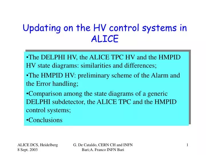
Updating on the HV control systems in ALICE. The DELPHI HV, the ALICE TPC HV and the HMPID HV state diagrams: similarities and differences; The HMPID HV: preliminary scheme of the Alarm and the Error handling;

E N D
Updating on the HV control systems in ALICE The DELPHI HV, the ALICE TPC HV and the HMPID HV state diagrams: similarities and differences; The HMPID HV: preliminary scheme of the Alarm and the Error handling; Comparison among the state diagrams of a generic DELPHI subdetector, the ALICE TPC and the HMPID control systems; Conclusions G. De Cataldo, CERN CH and INFN Bari;A. Franco INFN Bari
STATE DIAGRAM of a DELPHI HV sub-system with intermediate HV values G. De Cataldo, CERN CH and INFN Bari;A. Franco INFN Bari Kindly provided by A. Augustinus NOT indicated are trips during ramping
Crate(s) powered on and running,all channels “OFF”,no values loaded to hardware OFF State diagram for the HV of one DEPLPHI subdetector with NO intermediate HV values. The Configuring state is also shown. Read values from databaseand write them to hardware CONFIGURING Crate(s) powered on,all channels “OFF”,operational values loaded to hardware “Configured” Channels ramping between “Off” valueand operational (“On”) value (and v.v.) RAMPING_DOWN RAMPING_UP Crate(s) powered on,all channels on operational “On” values ON G. De Cataldo, CERN CH and INFN Bari;A. Franco INFN Bari Kindly provided by A. Augustinus
ALICE TPC Prototype II FSM Software PVSS Shift DCS SMI++ TPC HV LV Cool Gas edge digital module module sensor sensor anode analog fanout within PVSS Ch Ch Ch Ch Ch Expert Ch PVSS Kindly provided by U. Frankenfeld G. De Cataldo, CERN CH and INFN Bari;A. Franco INFN Bari
At least one channel tripped at voltages above INTERMEDIATE voltage HV HV The TPC HV state diagram OFF STOP_HW START_HW HW_READY CONFIGURE CONFIG CONFIGURE SET_CONFIGURATION CONFIGURE CONFIGURED CONFIG SET_CONFIGURATION STOP_HW START_HW GO_INTERMEDIATE GO_INTERMEDIATE SWITCH_OFF RECOVER ERROR NOT_READY RAMPING_DOWN RAMPING_UP START STOP SWITCH_OFF CONFIGURE SET_CONFIGURATION INTERMEDIATE CONFIG START RAMPING_DOWN RAMPING_UP STOP ON Kindly provided by U. Frankenfeld G. De Cataldo, CERN CH and INFN Bari;A. Franco INFN Bari
SMI Control Unit HMPID DCS SMI Device Unit HVPS1 PLC S300 Hardware Device The HMPID CS Architecture Working in progress Advanced Status External to the HMPID CS HMPID DCS HV LV LCS COOL GAS Phis. Par Cooling System Gas System HVMod 1 LVSctr 1 LCSMod 1 HVPS1 LVPS1 LCSMain LVPS1 CAEN SY1527 HV PS PLC S300 PLC S300 WIENER PL500F8 LV PS G. De Cataldo, CERN CH and INFN Bari;A. Franco INFN Bari
THE STATE DIAGRAM of the HV for one HMPID module OFF All channels off Go_Standby From any state upon Reset CONFIGURE Go_OFFGo_ON Reset #trips ≥ 4 Upon Acknowledge After the download of recipes all channels at Standby STANDBY At least one channel ramping up All channels at Standby Trips? Repair Acknowledge Reset Yes At least one ch tripped RAMPING_UP ERROR_REPAIR RAMPING_DOWN #trips < 4 #trips ≥ 4 At least onechannel tripped CH Trip? max? #trips < 4 At least onechannel tripped Go_RampDW Reset At least one channel ramping down X% of channels on ON G. De Cataldo, CERN CH and INFN Bari;A. Franco INFN Bari
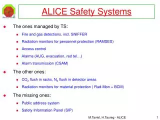
THE HMPID HV Subsystem ( 7 Modules) STATE DIAGRAM Go_Standby OFF All channels off With PS ON • Alarm conditions pushing the system in ERROR: • External Interlock (Gas, SS…) • Sy1527 fan tray failure • Sy1527 AC unit failure • Uncalibrated board • In this state all the HMPID HV channels are switched OFF. Repair Acknowledge From any state upon Reset ERROR CONFIGURE Go_OFFGo_ON Reset After the download of recipes all Modules are at Standby Alarm conditions STANDBY All Modules in Standby At least one Module is ramping up RAMPING_UP RAMPING_DOWN Go_RampDW Reset At least one Module Is ramping down ON G. De Cataldo, CERN CH and INFN Bari;A. Franco INFN Bari
The HMPID HV: preliminary scheme of the Alarm and Error handling G. De Cataldo, CERN CH and INFN Bari;A. Franco INFN Bari
Module HV: ERROR_REPAIR source 1 OFF All channels off Go_Standby From any state upon Reset CONFIGURE Go_OFFGo_ON Reset #trips ≥ 4 Upon Acknowledge After the download of recipes all channels at Standby STANDBY At least one channel ramping up All channels at Standby Trips? Repair Acknowledge Reset Yes At least one ch tripped RAMPING_UP ERROR_REPAIR RAMPING_DOWN #trips < 4 #trips ≥ 4 At least onechannel tripped CH Trip? max? #trips < 4 At least onechannel tripped Go_RampDW Reset At least one channel ramping down X% of channels on ON G. De Cataldo, CERN CH and INFN Bari;A. Franco INFN Bari
Module HV: ERROR_REPAIR source 2 OFF All channels off Go_Standby From any state upon Reset CONFIGURE Go_OFFGo_ON Reset #trips ≥ 4 Upon Acknowledge After the download of recipes all channels at Standby STANDBY At least one channel ramping up All channels at Standby Trips? Repair Acknowledge Reset Yes At least one ch tripped RAMPING_UP ERROR_REPAIR RAMPING_DOWN #trips < 4 #trips ≥ 4 At least onechannel tripped CH Trip? max? #trips < 4 At least onechannel tripped Go_RampDW Reset At least one channel ramping down X% of channels on ON G. De Cataldo, CERN CH and INFN Bari;A. Franco INFN Bari
Module HV: ERROR_REPAIR source 3 OFF All channels off Go_Standby From any state upon Reset CONFIGURE Go_OFFGo_ON Reset #trips ≥ 4 Upon Acknowledge After the download of recipes all channels at Standby STANDBY At least one channel ramping up All channels at Standby Trips? Repair Acknowledge Reset Yes At least one ch tripped RAMPING_UP ERROR_REPAIR RAMPING_DOWN #trips < 4 #trips ≥ 4 At least onechannel tripped CH Trip? max? #trips < 4 At least onechannel tripped Go_RampDW Reset At least one channel ramping down X% of channels on ON G. De Cataldo, CERN CH and INFN Bari;A. Franco INFN Bari
ERROR_REPAIR Panels G. De Cataldo, CERN CH and INFN Bari;A. Franco INFN Bari
HV HV HV HV HV HV LCS LCS LCS LCS LCS LCS LV LV LV LV LV LV M7 Summary of the HMPID HV Alarm and Error HANDLING To the ALICE ERROR Handling Sub-system ERRORs HMPID DCS GAS LV LCS HV M1 M2 M3 M6 M4 M5 ERROR HMPID ERROR active if the HV ERROR is active M7 HV LCS LV HV ERROR is active if: - EXT INTERLOCK; -SY1527 fan failure; - un_calibrated board. Any of these conditions will result in the HMPID HV=OFF. HV sub-system CS To the HMPID DCS ERROR Handling M1 M3 M4 M5 M6 ERROR . SY1527 The ERROR_REPAIR stateis active if one or all the module HV channels (sectors) are in trip.This state is not propagated to the HV subsystem but just a color coded information is sent to the HV subsystem and HMPID DCS level ERROR_REPAIR Module HV CS ? S1 M7 S6 G1 G. De Cataldo, CERN CH and INFN Bari;A. Franco INFN Bari
STATE DIAGRAMS STANDARDIZATION ? From the top level of a subdetector CS, the subsystem state diagrams(SD) and commands are transparent then the SD standardization is not mandatory. In turn, in order to operate simultaneously all the sub-detectors and easily calculate the ALICE DCS logical state, then it is mandatory to standardize the sub-detector DCS state diagrams. ECS YES DAQ ALICE DCS Standard State Diagrams Trigger TPC HMPID TPC DCS HMPID DCS TRD TRD DCS Sub-detector oriented State Diagrams HV LV NO TPC TR HMPID TR TRD TR G. De Cataldo, CERN CH and INFN Bari;A. Franco INFN Bari
Comparison among the state diagrams of a generic DELPHI subdetector, the ALICE TPC and the HMPID control systems. G. De Cataldo, CERN CH and INFN Bari;A. Franco INFN Bari
Main states and commands of one of DELPHI’s sub-detector G. De Cataldo, CERN CH and INFN Bari;A. Franco INFN Bari
TPC TPC DCS state diagram Kindly provided by U. Frankenfeld G. De Cataldo, CERN CH and INFN Bari;A. Franco INFN Bari
HMPID DCS State Diagram GO_STANDBY OFF ( Config Name) RESET RESET GO_STANDBY The command provides to the control system the “Name” of the configuration to be downloaded. FROM ERROR ANY CONFIG GO_OFF STATE NOT_READY The NOT_READY state is not yet All Sub defined Alarm System are Conditions Configured ! STAND : Not yet completely specified BY During the Count Down to READY State, All Sub System GO_READY in order to operate safely the detector, are in READY the commands to all the sub STANDBY ! systems are dispatched according to a Count Count defined sequence. This synchronization is Down to Down to ensured by the DCS control program. READY STANDBY All DCS Sub Systems are GO_RAMPDW READY READY ! G. De Cataldo, CERN CH and INFN Bari;A. Franco INFN Bari
Conclusions • From the top level of a subdetector CS, the HV,LV,..etc state diagrams(SD) and commands are transparent then the SD standardization is not mandatory; • In turn, in order to allow the ALICE DCS to simultaneously operate the sub-detectors and easily calculate the DCS global logical state, then it is mandatory to standardize the state diagrams and commands for eachsub-detector CS; • To prevent the sub-detector damaging during some LHC operation phases (very high event rate) then as done in the DELPHI DCS, also in ALICE some commands related to the LHC status (at present nobody knows!) has to be implemented: Prepare_for_injection, Prepare_for_shutdown……, • In order to start to prepare the ALICE DCS state diagram, each subdetector is kindly requested to provide the related DCS operating state diagram and commands! A combination of all these diagrams with the LHC states (and some other ingredients!)will provide the STANDARD STATE DIAGRAM FOR ALL THE SUBDETECTORS! G. De Cataldo, CERN CH and INFN Bari;A. Franco INFN Bari