Download
1 / 11
120 likes | 253 Views
MECO Cryogenic System. Overview. Helium System Steady state 4.5 k system Steady state heat loads and operating points Thermal design of Dewars TS and DS Thermal Design of PS Dewar Liquid N 2 System Quench Recool after Quench. Component Overview.

E N D
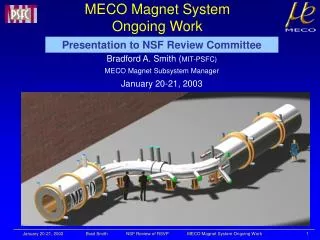
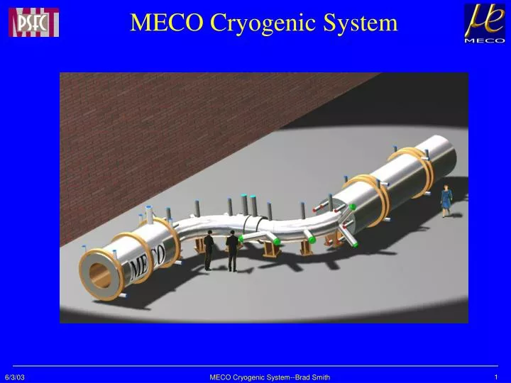
MECO Cryogenic System MECO Cryogenic System--Brad Smith
Overview • Helium System • Steady state 4.5 k system • Steady state heat loads and operating points • Thermal design of Dewars TS and DS • Thermal Design of PS Dewar • Liquid N2 System • Quench • Recool after Quench MECO Cryogenic System--Brad Smith
Component Overview • Four Separate Cryostats (PS, TS1, TS2 and DS) • One Liquefier/Refrigerator • Pressurized Liquid Nitrogen Tank-(Truck filled) • Forced Convection cooling in 3 dewars (TS1, TS2 and DS) • Conduction cooling from He tubes to the coils (No He bath) • PS is pool cooled- Natural convection and/or Forced flow cooling. • Two storage/control dewars • Vacuum insulated LN2 traced MLI. MECO Cryogenic System--Brad Smith
Design and Operation Overview • All active components are outside the shield wall. • Many interconnections and valves to allow for flexible operation. • Dewars can be cooled separately. • Cooling of one dewar does not affect the state of other dewars. • Valves allow the isolation of cryostats during a quench. • Cool down with He circulated from and LN2 heat exchanger for T>80 K. • Cool down with He from the liquefier for T<80K. • Dewars are protected against overpressure during a quench. MECO Cryogenic System--Brad Smith
Steady State Operation MECO Cryogenic System--Brad Smith
Estimated Heat Loads MECO Cryogenic System--Brad Smith
States in Cooling System MECO Cryogenic System--Brad Smith
Cryostat 4.5 K Cooling PS • Bath cooled with 6700 liter LHe volume to safely remove 192 W of nuclear heat load at 4.5 K • 25 cm diameter quench vent stack keeps quench pressure below 5 atmospheres TS and DS • Lack of nuclear heat load enables conduction cooling • Inner and outer copper shells intercept radiation heat load and take it to He-traced copper heat sinks at the top of each coil All cryostats have stainless steel vacuum shells and LN2-cooled thermal radiation shields. MECO Cryogenic System--Brad Smith
He Vessel Pressure for PS Quench MECO Cryogenic System--Brad Smith
Estimates of cooldown times Cooldown MECO Cryogenic System--Brad Smith
Liquid Nitrogen System • Tank filled by commercial vendor • LN2 distribution lines cool shields in 4.5 K conduits. • LN2 cools heat stations on valves and vacuum separators. • Commercial MLI systems combined with an LN2 shield is used for lines, cryostat and dewars. • LN2 cooled heat stations on mechanical supports in PS, DS and TS. • ~~More details on the Ozone issue in a later talk~~ MECO Cryogenic System--Brad Smith