Download
1 / 24
250 likes | 299 Views
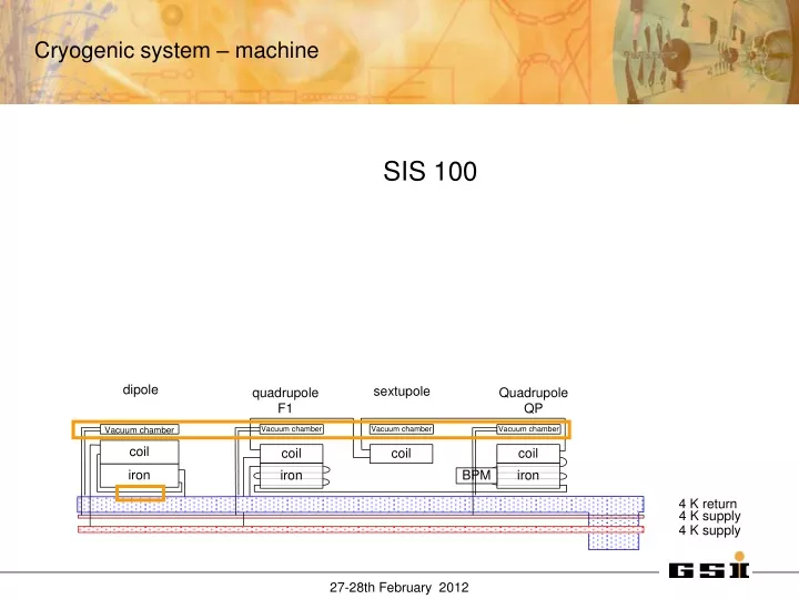
Cryogenic system – machine. Vacuum chamber Recooler String system Components. SIS 100. Cryogenic system – SIS100 vacuum chamber. Voltage breaker. ~16 K. ~ 5.5 K. Heat load ~10W/m. Courtesy S. Wilfert, UHV group. Cryogenic system – SIS100 vacuum chamber.

E N D
Cryogenic system – machine • Vacuum chamber • Recooler • String system • Components • SIS 100
Cryogenic system – SIS100 vacuum chamber Voltage breaker ~16 K ~ 5.5 K Heat load ~10W/m Courtesy S. Wilfert, UHV group
Cryogenic system – SIS100 vacuum chamber Maximum allowed average beam vacuum pressure under dynamic conditions must bep < 10-11 mbar is given by beam life time Chamber wall temperatures in cryogenic sections will range from 5K…15K • Cryopumping is used for generation of UHV pressures in the beam vacuum system • Effective cryopumping requires wall temperatures lower than 15K • At temperatures lower 15K all easily condensable gas species can be effectively cryo-condensed on the cold beam pipe wall • Excepting H2 and He, the saturation vapor pressures of all vacuum- relevant gas species at 15K are lower than 10-12 mbar, and thus are negligible Courtesy S. Wilfert, UHV group
Cryogenic system – SIS100 vacuum chamber Dpsupply=0.015 bar ~ 9.8% Therefore the diameter choice of DN 25 is reasonable
Cryogenic system – SIS100 recooling 1000 W/m2K ~ 170 W/m2K
Cryogenic system – SIS100 recooling The heat load on the supply line within on cell (12m) has to be below .5 W. As the line is only supported by the cold iron this can be achived.
Cryogenic system – SIS100 dipole Temperature at the outlet of magnet Max. Temperature at the coil of magnet Void fraction at the outlet of magnet
Cryogenic system – SIS100, string QP DP + Dipole Quadrupole Static dynamic dipole 5 33,9 q.pole 4 19 correc. 0 5 vacu.Ch. 0 10,6
d m s Cryogenic system – SIS100 , string ps = 1,1 bar pd = 1,5 bar Tm = 4,5 K u = Gs/Gm pm=3 bar u = 0,73 Recycling by ejector, below 17 W additional heater
Cryogenic system – SIS100 , string Thermo-hydraulic mock-up Unfortunately the test could not started by now, due to a delay in delivery and a failure in the refrigerator; but it was already a successful training for the dipole manufacturer. Tests will follow.
Cryogenic system – SIS100, cool down magnet itself - by convection, helium flow through magnet (no helium flow passes through supply and return line) in machine - the full equipment has a design pressure of 18 bar, therefore during cool down the supply pressure can be increased up to 18 bar to increase the mass flow through the magnets. For this operation the recooler can transfer heat of ~80 W (@DT=50K). - by suppling the supply line by the shield line from the endbox side the cool down can be equalized. - magnet cooled by convection (and conduction) - the maximal mass flow available for cool down is given by a) the pressure drop in the system (designed for 1000 g/s triangular cycle) b) the available cooling capacity of the refrigerator ( ramp duty .5) Cool down time : ~ 9 d (depending on the final cold mass)
Cryogenic system – SIS100 Vacuum barrier Max. length of section of insulation vacuum: 150 m An each sector have to be cooled down/ kept cold independently
Cryogenic system – SIS100 End box To minimizes the feed-troughs no valve systems with positioners with external potentiometer
2.8.12.5 Cryogenic bypass line(including Bus Bars) Shorter version The maximum length of one continuous vacuum is ~150m. Each sector should be kept cold independent. End box Terminates helium flow Cool-down/warm up connections Bus bar connection feed in Supplies helium flow Electrical supply and/or bus bar connection By pass line helium connection bus bars => with vacuum barrier Amount: 10 (+2) 6 3 1 +2
Cryogenic system – SIS100 By-pass line Connection box Feed out: CWT Transferring helium lines and bus bars into the bypass line Soldering of busbar connections Support of pressurized tubes (bends) End caps: Termination of the cold section => CWT Flipped version Magnet version: CWT Transfer of two QP bus bars Soldering of bus bar connections Feed trough of by-pass lines Amount: 6 (+4 Ref.mag) 6 6 14 +4 extended
Cryogenic system – SIS100 By-pass line 2.8.12.5 Cryogenic bypass line (including Bus Bars) Shorter version The maximum length of one continuous vacuum is ~150m. Each sector should be kept cold independent. End box Terminates helium flow Cool-down/warm up connections Bus bar connection feed in Supplies helium flow Electrical supply and/or bus bar connection By pass line helium connection bus bars => with vacuum barrier Amount: 10 (+2) 6 3 1 +2
Cryogenic system – SIS100 Electrical Supply The two bus bars of one electrical circuit are one hydraulic line. One bus bar will be supplied by supercritical helium (2.95 bar, 4.4 K). Within the current lead box part of the helium stream will by throttled into a recooler. The recooler provides liquid helium at 4.4 K for the second bus bar of the circuit. The helium vapour from the recooler will be fed into a separate line down to the transfer line towards the refrigerators at tunnel level. This return line is a common one for all recooler in the feed box. The two bus bars of one electrical circuit are in parallel. The return of the helium is in a separate line. Both bus bars will be supplied by supercritical helium (2.95 bar, 4.4 K). To keep the return supercritical the pressure drop of the return line may be lowered in respect to the cable by increasing the diameter. As a third option this scheme could be operated in the two-phase region, as bubbles always can travel to the top
Cryogenic system – SIS100 Testing • Component test and assembly test are required for: • Bypass line including vacuum barrier with busbar system • Electrical supply system • These test should consist from an individual component test and a system test • (at string test facility) • Feed box may be assumed as a reliable 4K design.
Cryogenic system – SIS100 control Cryogenic control Current lead control