Download
1 / 43
430 likes | 531 Views
Steering algorithm experience at CTF3. Davide Gamba davide.gamba@cern.ch 13 December 2013 (Slides from previous presentation at The International Workshop on Future Linear Colliders LCWS13). Outlook. CTF3: the CLIC Test Facility at CERN. Steering necessities.

E N D
Steering algorithm experience at CTF3 Davide Gamba davide.gamba@cern.ch 13 December 2013 (Slides from previous presentation at The International Workshop on Future Linear Colliders LCWS13)
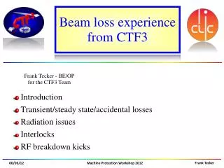
Outlook • CTF3: the CLIC Test Facility at CERN. • Steering necessities. • A general feedback algorithm and its implementation. • Preliminary resultsand issues. • Work in progress: new tools. • Dispersion measurement from Jitter. • “Jitter free steering.” • Summary.
CTF3: the CLIC Test Facility at CERN. Drive Beam Gun Dogleg Experiment Factor 2 Recombination Factor 4 Recombination Building 2003 DL 42 [m] Building 2001 CR 84 [m] Building 2010 Building 2013 CLEX area Probe Beam Photo-Injector Photo Injector Tests Two Beam Test Stand (TBTS) XBOX experiment Deceleration Test Beam Line (TBL)
Steering necessities. • For machine operation and optimization we need a general tool to control the orbit of the beam. • It has to deal with some intrinsic limitations • Data acquisition is affected by noise • White noise • Not null dispersion and energy jitter • Non responsive control system • Delicate Front-Ends • Instable beam (mainly coming from RF instabilities) • Beam position may not be a well defined measurement in case of losses • Challenging machine • MADX model not always accurate • Aperture limitations • Algorithm to measure the response matrix needed • Has to be “fast” compared to machine faults and drifts • Has to be able to follow slow drifts of the machine
Steering necessities. They don’t necessarily come back on the same trajectory. Only one section over two is delayed into the Delay Loop • Special case: during recombination, different section of the initial train take different paths. Initially we only have a long train “divided” into 8 sections, each 140 ns long Projected emittance blow-up. Increased losses. In the Combiner Ring all the 8 sections can end up in having different orbits
Steering necessities. Use correctors in Delay Loop Force the same orbit in the next Transfer Line (TL1) • First stage: match orbits of delayed and not-delayed trains. • In principle only two correctors with the right phase advance are needed. • Aperture limitations may impose to use more correctors.
The algorithm • Solving a linear system of equations
The algorithm SVD Synchronization
The algorithm • Measure the response matrix based on a simple concept: • Randomly excite all the correctors • Read the Beam Position at all the interested points • Invert the same linear system of equations, but the Response Matrix is now the unknown: • Keep a history of last setting/observations pairs of variable length • Also during beam corrections outcome data can be used to improve Response Matrix.
Testing the response matrix measurement algorithm Real response matrix Computed response matrix Computed – Real • N correctors = 8 • N BPMs = 12 • correctors excitation σ = 1[A] • correctors noise σ = 0.01[A] • BPMs noise σ = 0.1[mm] • dispersion induced jitter σ = 1 [mm] • number of iterations: 100 • history size: n = 30.
The algorithm: implementation and test • Developed a Matlab application for generic linear feedbacks.
The algorithm: implementation and test • Example of correction of beginning orbit of the linac.
The algorithm: implementation and test • Example of use to control end of linacorbit:
The algorithm: implementation and test • Example of use to control end of linac orbit:
The algorithm: implementation and test • Example of use to control end of linac orbit:
The algorithm: implementation and test • Example of use to control end of linac orbit:
Preliminary results • Back to the main goal: • use the tool to match “delayed” and “straight” orbits in TL1. Use correctors in Delay Loop Force the same orbit in the next Transfer Line (TL1)
Preliminary results “Orbit matching” in TL1
Preliminary results • A first issue: straight and delayed beam have different energy • From a rough estimation, this offset is related to a • Δp/p = -0.03 of the delayed beam. Note: the injector was not properly optimized. These results were not obtained in normal condition of operation.
Interlude: beam jitter induced by energy jitter • After summer shutdown: looking at energy jitter markup in beam position in dispersive region. • We are affected by a natural jitter of the energy. • Beam energy along the pulse is also not always flat. • Thanks to generality of our feedback tool we can use it to shape the RF power of last linac structure to try to compensate the second effect. Note: 3Ghz beam for factor 4 recombination, i.e. different setup respect to previous slide!
Dispersion measurement from Jitter • Developed an application to passively measure dispersion by beam jitter.
Jitter free steering Nominally non zero dispersion Nominally dispersion free • The first area where we have dispersion is at the end of Drive Beam linac, where a chicane is installed.
Jitter free steering • Using the same feedback application and measuring dispersion as jitter. • Change correctors inside chicane to reduce jitter (i.e. dispersion) downstream. • Acquiring 30 beam pulses for each iteration. • Main disadvantage: RM measurement and correction takes longer time. Preliminary results!
New ideas • Other ideas to get read of energy jitter to measure Response Matrices? • Even better: use it in a different way to get Dispersion Response Matrix. • Can we guess the beam main characteristics ( x0 ; x0’ ; Δp/p ) only looking at the orbit of the beam in few BPMs upstream, and predict the orbit downstream? • What if in the mean time a corrector is changed (and so the dispersion)? Use as indipendent variables the BPMs readings in TL1 In the mean time randomly excite downstream correctors (also indipendent variables) • In a system like this, at first order, beam position in a downstream BPM seems to linearly depend on: • x0 ; x’0 ; Δp/p ; • (Δp/p x0) ; (Δp/p x’0) ; • IC1 ; (Δp/p IC1) ; … ; ICN; (Δp/p ICN) • We don’t have any of this information, but they may be expressed in terms of upstream beam positions. Measure response matrix downstream
New ideas • If we suppose that within two shots we only change correctors and energy. • Δ(Δp/p) can be measured from the jitter on a BPM. … Work in progress to verify this is correct …
Summary • What has been done: • Developed and tested a generic linear feedback. • Smart way to measure the response matrix: it can work in quasi-parasitic mode and/or during orbit correction. • First results and characterization of possible limitations. • What is ongoing: • Dispersion measurements from jitter. • “Jitter free” steering. • Comparison of the response matrix with machine model (MADX). • e.g.: found a corrector with inverted polarity. • Model optimization using LOCO procedures. • What is next: • Demonstrate the possibility to match the two orbits in TL1 within noise level. • Apply the feedback for the full closure of CR. • Measure the improvement in beam emittance and power production stability.
DL -> Tl1 Response Matrix (Appendix) • MADX and Measured RM
DL -> Tl1 Response Matrix (Appendix) • MADX and Measured RM
DL -> Tl1 Response Matrix (Appendix) • MADX and Measured RM
DL -> Tl1 Response Matrix (Appendix) • MADX and Measured RM
DL -> Tl1 Response Matrix (Appendix) • MADX and Measured RM
DL -> Tl1 Response Matrix (Appendix) • MADX and Measured RM
DL -> Tl1 Response Matrix (Appendix) • MADX and Measured RM
DL -> Tl1 Response Matrix (Appendix) • MADX and Measured RM