Download
1 / 32
320 likes | 396 Views
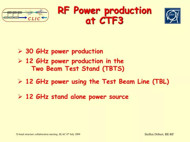
RF Power production at CTF3. 30 GHz power production 12 GHz power production in the Two Beam Test Stand (TBTS) 12 GHz power using the Test Beam Line (TBL) 12 GHz stand alone power source. Rf power production with CTF3. X 2 Delay Loop. 4 A - 1.2 m s 1.5 GHz, 150 MeV.

E N D
RF Power production at CTF3 • 30 GHz power production • 12 GHz power production in the Two Beam Test Stand (TBTS) • 12 GHz power using the Test Beam Line (TBL) • 12 GHz stand alone power source
Rf power production with CTF3 X 2 Delay Loop 4 A - 1.2 ms 1.5 GHz, 150 MeV Drive Beam Accelerator Drive Beam Injector 16 structures - 3 GHz - 7 MV/m X 4 Combiner Ring 30 GHz Test stand 30 A - 140 ns 12 GHz, 150 MeV Probe Beam Injector 65 MW, 100 ns Two Beam Test stand12 GHz 200 MW, 140 ns TBL, 16*150 MW, 140 ns Stand alone 12 GHZ test stand in CTF2, 50 MW klystron + pulse compressor
30 GHz Power Production Up to 60 MW for testing 36% Power lost in ‘Translation’ Up to 100 MW out of PETS
Automatic conditioning Pulse to pulse data acquisition for history and waveforms for trips
Automatic conditioning, strategy and interlocks Programmable trip detection method and switch on procedure
The 12 GHz PETS E max (135 MW)=56 MV/m RF power density H max (135 MW)=0.08 MA/m One of the eight PETS bar
To the Load Variable Splitter (coupling: 01) Variable phase shifter PETS output CTF3 PETS input #1 Drive beam DL CR DBA CTF2 TBTS CLEX #2 #3 PETS high power test in the TBTS • Different drive beams generated in the CTF3 Round trip efficiency: 75% Round trip delay: 22 ns <30A 1 m 14 A Expected PETS power production with re-circulation. The calculation followed the measured performance of all the components CLIC nominal 6.0 A 4 A 5.0 A 4.0 A 3.5 A 240 ns CLIC nominal I. Syratchev
1 m long TBTS PETS Two Beam Test Stand (TBTS) Fully equipped 1 m long TBTS PETS Variable high power RF power splitter Drive beam Variable high power RF phase shifter PETS tank with re-circulation RF circuit installed in TBTS test area (October 2008) I. Syratchev
PETS processing PETS processing history in 2008 15.11.08 14.12.08 Conditioned to about 30 MW, 150 ns flat top
High power test, first results Model with constant coupling and phase Event with breakdown Pmod = c2Pmeas = (0.78)2Pmeas (bunch length 2.8 mm rms) E. Adli
PETS testing Klystron Drive beam RF power in RF power out RF power out Drive beam CTF3 (CERN + Collaborations) ASTA (SLAC) Two beam test stand (CERN + Collaborations) Objective: to understand the limiting factors for the PETS ultimate performce Objective: to demonstrate design rf parameters at the output of the PETS What matters is the output section ! Test beam line (CERN + Collaborations) Objective: to demonstrate the beam transportation without looses and ~ 50% deceleration. I. Syratchev
Test Beam Line Goals • High energy spread beam transport, low losses (Bench mark simulations) • RF Power Production, Stability (End Energy <50%, 2.4 GW of RF power) • Alignment Active Quad alignment with movers (Test procedures for BBA, DFS) 100 microns pre-alignment for PETS • Drive Beam Stability, Wake fields (no direct measurement of the wake fields) • ‘Realistic’ show case of a CLIC decelerator • Industrialization of complicated RF components
PETS tank assembly, CIEMAT Happy Team after finishing the first tank
Prototype module installed in April 2009 PETS-tank, CIEMAT Quad, BINP BPM,IFC, UPC, LAPP Quad Mover, CIEMAT
TBL planning • Organize and launch production of at least 7 more PETS with our collaborations to be commissioned with beam in 2010. Approach: parallel fabrication at CIEMAT and CERN using multiples vendors • CDR demonstration measurement milestones at the end of 2010 • Complete TBL with 16 PETS in 2011 • Full demonstration of drive beam decelerator end of 2011 • > 2012 use TBL as a 12 GHz power source, rf conditioning with beam ( up to 16 testing slots would be possible)
TBL energy profile 16 PETS E0 = 150 MeV I=28 A Energy extraction: 56 % 2.2 GW of rf power
12 GHz Test-Stand at CERN Stand alone 12 GHZ test stand with independent bunker (CTF2) and option to use the power synchronized with beam in CTF3 50 MW klystron form SLAC, pulse compressor from the beginning K. Schirm, F. Peauger
Modulator Control PCB, Sol PS, Vac PS, RF equippment HVPS, New place Primary Power Connections Cooling System Transformer Tank Flow Guards Filament PS Core Bias PS Oil Pumps/Filter Status: ordered
Pulse Compressor: Gycom irises TE – TE 10 01 converters 3 - dB coupler Two modes (H01+H02) mode mixing taper Courtesy: I. Syratchev Status: ordered
Schedule Goal is to be operational in Summer 2010
Conclusion • 30 GHz power source will stop operating at the end of this year We basically finished our testing program at 30 GHz • TBTS will come online in fall with a first 12 GHz structure test and two beam acceleration experiments. It will be challenging to operate at the beginning • TBL should produce power soon and is effectively a test for PETS but the power will be used only after 2012 for accelerating structure testing • The 12 GHz klystron based test stand should be available in summer 2010 and is considered as the new work horse for CLIC structure testing. We are already thinking of a klystron based structure testing plant with of the order of 10 testing slots
Outlook on CERN structure testing Up to 2010: CLIC feasibility testing, rely on collaboration with SLAC and KEK at 11.4 GHz 2011 -2012: ~ 6 structure tests/year at 12 GHz, stand alone test stand + a few in the TBTS 2013 -2016: In case we enter into the TDR phase TBL as power source Klystron base structure testing plant Goal: ~ 50 structure tests/year
TBL beam dynamics 1m ~ 3 ns
HOM damping in PETS T3P T3P T3P
Tunable reflector PETS ON PETS OFF Ramped pulse example. For the beam loading compensation. 0.25 PETS ON/OFF The choke-based reflector concept. ON OFF ON Rectangular pulse. Full system GDFIDL simulations • With proposed scheme we can guarantee the strong (< -20 dB) suppression of the RF power delivery to the accelerating structure. • In a case of the breakdown in PETS the RF pulse time structure and 25% saturated power allow to expect the PETS safe behavior. 0.25 OFF
PETS ON/OFF 2 ON 3 The short position in choke moved by 5.4 mm 1 OFF
As a result of multiple compromises, the PETS aperture a/λ = 0.46 (m = 2) was chosen. Drive beam Quad PETS PETS 100 A 2.4 GeV 0.24 GeV (0.87 km) Deceleration: ~6MV/m 131.5 MW 240 ns Main beam 1.2 A 9 GeV 1500 GeV (21 km) Acceleration: 100 MV/m Accelerating structure x4 PETS design P – RF power I – Drive beam current L – Active length of the PETS Fb – single bunch form factor (≈ 1) PETS cross-section The PETS are large aperture, high-group velocity and overmoded periodic structures. In its final configuration, PETS comprises eight octants separated by 2.2 mm wide damping slots.
Status • Installation of prototype beam line completed, waiting for beam (3 Quads on movers, 3 BPM’s and 1 PETS tank with undamped PETS) • Beam line without PETS tanks will be finished this fallPrototyping: • PETS tank: engineered and manufactured by CIEMAT (low level measurements performed and accepted) • BPM’s: smaller version of CTF3 type BPM, made by IFC Valencia Electronics from UPC Barcelona and LAPP Annecy ( basic tests with beam done) • Quads: Designed at CERN and manufactured by BINP Russia • Quad-Movers: engineered and manufactured by CIEMAT (tests demonstrated the micron level accuracy)
Experiments in TBL • Produce nominal 28 A beam and nominal CLIC power (135 MW) with at least 8 PETS and 100% transmission (120 MeV from CTF3) This corresponds to 35 % power extraction • Beam based quad alignment with movers to optimize transmission and transverse beam parameters • Detailed energy and energy spread measurements to verify deceleration. • Streak camera measurements before and after TBL • Monitor rf power production stability, amplitude and phase (% level in amplitude, 1 degree in phase) • Measure beam properties and compare with simulations • Controlled misalignment of quads, measure effect ? • Controlled beam offset in PETS, measure effect ?