Download
1 / 13
130 likes | 135 Views
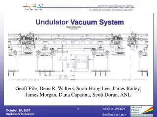
Undulator Vacuum Chamber. Geoff Pile Dean R. Walters Soon-Hong Lee, James Bailey, James Morgan, Dana Capatina , Scott Doran, ANL. Undulator Vacuum System. Undulator Vacuum Chamber Prototypes Prototype Construction Testing of Prototypes Production Initial Production Tasks

E N D
Undulator Vacuum Chamber Geoff Pile Dean R. Walters Soon-Hong Lee, James Bailey, James Morgan, Dana Capatina, Scott Doran, ANL
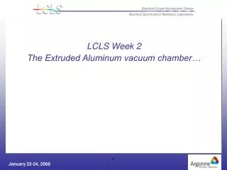
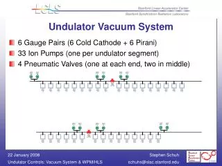
Undulator Vacuum System • Undulator Vacuum Chamber • Prototypes • Prototype Construction • Testing of Prototypes • Production • Initial Production Tasks • Magnetic Field Measurements • Reconsideration of Stainless Steel • Aluminum Clamshell • Aluminum Extrusion • Copper Tube
NW 50 Flange -Clamp Type (316L SST) Compound screws (Brass Screws & SST ) Vacuum Chamber Chamber Strong-back (316 SST) Chamber Strong-back (20Cb-3) Top & Bottom Strips (20Cb-3) Top & Bottom Strips (316LN) End Cap (20Cb-3) End Cap (20Cb-3) Prototype Vacuum Chambers Prototype A Prototype B
Production Chamber Permeability (full length Prototype A) As-received Alloy 20 1.009 ~ 1.010 (0.75” thick) After fabrication, permeability 1.013 [spec: 1.02]
12 Foot Test – 2/2/2007 Sample Location Sample Location
Coating Results • Test were performed by inserting silicon samples into 13 mm ID SST spool. Each test had four samples down the length. In most cases the samples were measured in more than one location • Uniformity down the length • In three different tests over the 12 foot length • Test #1: Average thickness of 98 nm with uniformity of 10% • Test #2: Average thickness of 325 nm with uniformity of 4.3% • Test #3: Average thickness of 210 nm with uniformity of 12% • Results of surface finish • Test #1 surface increased roughness by 1 nm • Test #2 surface roughness was unchanged by the coating • Test #3 surface increased roughness by 2 nm Plans for further measurements
Baking the Prototypes Measurements of Vacuum Performance(Outgassing Rate Spec: 2x10-12 Torr-Lit/sec/cm2) Prototype B PrototypeA • Proto B • Base Pressure : 5.9x10⁻⁹ / 1.1x10⁻⁹ • Outgassing Rate : avg. of 6x10-13 Torr-Lit/sec/cm2 • Proto A • Base Pressure : 2.2x10⁻⁹ / 2.5x10⁻⁹ • Outgassing Rate : avg. of 3x10-13 Torr-Lit/sec/cm2 Baking of Prototypes A and B • Proto B • 1st bake (before coating) at 200 deg C • 2nd bake (after coating) at 150 deg C • Proto A • 1st bake (before coating) at 150 deg C • 2nd bake (after coating) at 150 deg C
X-Adjustor Z-Adjustor Support Assembly Production Vacuum Chamber Ass’y Vacuum Chamber Assembly
Preparations for Production • Support Assembly • SOW completed • This is awarded • Chamber Material • Alloy 20 for first 11 units in house • Purchase for next 26 on “Hold” • Side Wall • SOW is complete • Vendor has made initial part using water jet cutting • Purchase is on “Hold” • Strongback • SOW is complete • Purchase is on “Hold” • End Cap • SOW is complete • Purchase is on “Hold” • All drawings for the chamber and the support have been completed and released. • Minor updates have been incorporated. • Tooling has been made, and used, for: machining the strongback, laser welding, and final machining.
Conclusions • Two full sized prototypes have been built. • All planned fabrication steps have been performed. • Seam Welds were performed by Laser Welding. • Even though leaks were found, they have been repaired. • The vendor is organizing further work to address them. • Construction of the 12 foot fixture and initial development of the AC Diode Sputtering process has lead to Aluminum coatings applied to both prototypes. • The chambers have been baked and their measured outgassing rate is lower than the specification
Ratio between field change due to the vacuum chamber and the field strength ANL Measurements Variation at ~8 gauss I. Vasserman & L. Moog, ANL Note that the y axis is in parts times 10-4. The allowed variation between an undulator’s field (overall) and its desired value is 1.5 x 10⁻⁴.
Measurements taken by SLAC Magnet Measurement facility SLAC Measurements Variation at ~8 gauss This is agreement with ANL measurements Andrew Fisher, SLAC
Risks associated with Stainless Chamber Permeability • Heinz Dieter will now explain the physics issues