Download
1 / 51
570 likes | 859 Views
LCLS Undulator Vacuum Chamber. Internal Design Review. Soon-Hong Lee Dean R. Walters. Contents. Overview Conceptual design Undulator vacuum chamber Support assembly Adjustment mechanism Weight estimation FE stress analysis Vacuum chamber Support Construction study Polishing

E N D
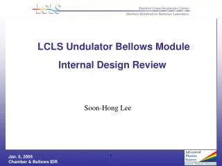
LCLS Undulator Vacuum Chamber Internal Design Review Soon-Hong Lee Dean R. Walters
Contents • Overview • Conceptual design • Undulator vacuum chamber • Support assembly • Adjustment mechanism • Weight estimation • FE stress analysis • Vacuum chamber • Support • Construction study • Polishing • Forming • Welding • Coating • Flange selection • Chamber Testing Process • Schedule and Cost
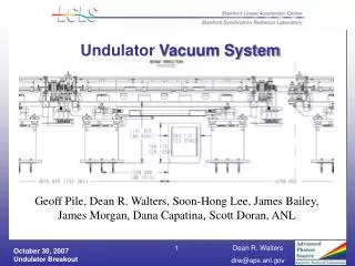
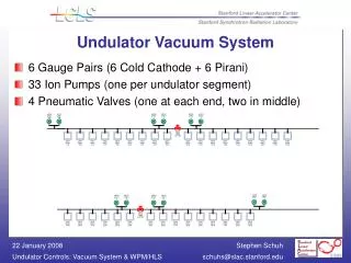
3,400 470 898 Undulator 12,038 mm Total undulator length (x11): 131.52 m Beam Position Monitor Beam Finger Wire X-Ray Diagnostics Quadrupoles Overview • Fabrication plan for vacuum chamber: • 33 production vacuum chambers & 7 spares • 1 mock-up chamber for single undulator test • 1 vacuum chamber for prototype
Contents • Overview • Conceptual design • Undulator vacuum chamber • Support assembly • Adjustment mechanism • Weight estimation • FE stress analysis • Vacuum chamber • Support • Construction study • Polishing • Forming • Welding • Coating • Flange selection • Chamber Testing Process • Schedule and Cost
LCLS Vacuum Chamber Ass’y Vacuum Chamber Assembly Support Assembly X-Adjustor Z-Adjustor
Vacuum Chamber Assembly Compound screws (SST/Brass or others) NW 50 Flange -Clamp Type (316L SST) Vacuum Chamber (316LN / 20Cb-3 SST) U-profile Al-coated SST Laser Welding Chamber Strong-back
Support Assembly C90200 Bronze Bushing Plate 304 SST Welded Rectangular Tubing ( 8˝ x 3˝ x 0.180˝)
Vacuum Chamber Adjustment Mechanism Compound screws - 5/8-18 screw - 7/16-20 screw • Y Vertical Adjustment - Compound screws • Total 26 threaded holes • 14 screws for vertical adjustment • Other 12 threaded holes for lifting / adjustments • X-Z Horizontal Adjustments – Cap screws X-adjustment5/16-18 screw Z-adjustment ¼-20 screw
Contents • Overview • Conceptual design • Undulator vacuum chamber • Support assembly • Adjustment mechanism • Weight estimation • FE stress analysis • Vacuum chamber • Support • Construction study • Polishing • Forming • Welding • Coating • Flange selection • Chamber Testing Process • Schedule and Cost
Aperture Maximum Displacement Maximum Stress Remarks 10 mm (H) x 5 mm (V) – Strip 0.52 m 8.15MPa Acceptable 15 mm (H) x 5 mm (V) – Strip 5.86 m 41.7MPa Acceptable 20 mm (H) x 5 mm (V) – Strip 19.2 m 106.4MPa Out of criteria 10 mm (H) x 5 mm (V) – U-profile 2.22 m 35.8MPa Acceptable 12 mm (H) x 5 mm (V) – U-profile 3.72 m 42.1MPa Acceptable 15 mm(H) x 5 mm (V) – U-profile 9.40 m 84.2MPa Out of criteria 20 mm (H) x 5 mm (V) – U-profile 27.3 m 115.7MPa Out of criteria • FE Analysis – Beam Aperture Ratio U-profile • Criteria • V = 5 mm • H 7.5 mm (50% greater than V-aperture) • Maximum Displacement < 10 m • Maximum Stress < 69MPa -Safety factor (3.0) w.r.t. yield stress (207MPa) ofSST V=5.0 mm H=? Strip V=5.0 mm H=?
Global Sensitivity Study – Strip type Max. von Mises stress vs. horizontal aperture / Max. displacement vs. horizontal aperture 69 MPa 10 m 16.7 mm 16.5 mm • FE Analysis - Global Sensitivity to Aperture Size
FE Analysis – Chamber • Loads • Vacuum pressure(1atm) = -0.1014MPa • Flange Weight = -2.0 N • Gravity = -9,810 mm/sec2 • Boundary Conditions • Model 1 - all bottom surfaces for 14 screws are fixed • Model 2 • 14 thread surfaces are fixed • 26 thread surfaces are fixed Model 2- without Screws Model 1- with Screws
FE Analysis Aperture 5.0 mm 6.0 mm 10.0 mm 1.5 mm Real Aperture 2.5 mm 5.0 mm 6.0 mm 7.5 mm 4.0mm FE model – Aperture Assumption
-144 m +144 m +144 m Case Study Model 1- with Screws Model 2- without Screws
x 100 Case 1
Case 3 x 100
Case 6 x 100
FE Analysis - Support • Loads • Gravity = -9,810 mm/sec2 • Weight of chamber Ass’y = -2,000 N on top surface
Contents • Overview • Conceptual design • Undulator vacuum chamber • Support assembly • Adjustment mechanism • Weight estimation • FE stress analysis • Vacuum chamber • Support • Construction study • Polishing • Forming • Welding • Coating • Flange selection • Chamber Testing Process • Schedule and Cost
Manufacturing Processes SST Sheet (144” x 2” x 0.118”) SST Plate (144” x 6” x 1”) Milling/Polishing Polishing/Grinding Al-Coating Al-Coating Forming Laser Welding Milling/Grinding
Technical Challenges • Polishing – surface roughness • 100~200 nm Ra (#8 mirror-finished) • Al-coating – thickness/uniformity • A layer of 100~150 nm • Forming – flatness/spring-back • Any damages on Inner surfaces • Flatness due to spring-back • Tooling design (die/punch) for 12-ft-long forming • Welding – penetration depth/heat-affected-zone • Laser welding/E-Beam welding for less weld distortion and leak tight • Tooling design (welding head motion control) for 12-ft-long weld • Final machining of chamber weldment • Wall thickness of 0.5 mm (grinding/milling) – waveness / uniformity • Geometric tolerance of flat surface ( 100 m) • Straightness of the strong-back plate (200 m) • Vertical adjustment mechanism for installation and alignment • Compound screw mechanism works fine or another option
Polishing of Stainless Steel • ANL bought samples of stainless steel sheets from Pacific Plus of Dallas, TX. • Pacific Plus specifies the surface to be 1 µin Ra (25 nm Ra). • Samples of 1.5 mm thick 316 SST sheets (1 ft x ft) and 0.5 mm thick 304 SST sheet (4 ft x 8 ft) were bought to evaluate the impact of manufacturing operation on the surface finish. • Samples for the Bending test were made from this material. • Samples (1″ x 1″) were measured on a Tencor Alpha-Step to obtain a 2D surface profile.
Polishing of Stainless Steel • Samples 0.5 mm thick Type 304 Stainless Steel Ra=207 Ǻ Ra=140 Ǻ(Sample is turned 90) Ra=147 Ǻ Ra=140 Ǻ Samples 1.5 mm thick Type 316 Stainless Steel Ra=1043 Ǻ Ra=149 Ǻ(Sample is turned 90) Ra=289 Ǻ Ra=97 Ǻ White Graph is a 5 m filter (default) Green is a band-pass filter of 5 m & 0.8 mm
Bending of Stainless Steel • Object of Tests was to investigate any damages to surface area • With the bending tooling, sample parts were made • V-Block, full-radius, and 1.5 radius female dies – related male punches
Bent Samples of Stainless Steel • To measure the roughness, bent samples were cut by wire-EDM • Also, flat samples were provided to compare the results • Measured by MicroXAM RTS surface profiler in the vertical scanning white light interferometry mode.
Surface Roughness of Flat Samples For each sample, the values shown are average of four measurements Picture B2 Picture B1 Picture A2 Picture A1
Surface Roughness of Bent Samples For each sample, the values shown are average of four measurements Surface finishes with thinner sheets (0.5 mm) showed better than thicker sheets(1.5 mm). Surface finishes with large bent radius (R=2.5 mm) showed better than small bent radius (R=1.5mm).
Picture 4 Picture 1 Picture 2 Picture 3 Picture 8 Picture 7 Picture 6 Picture 5 Surface pictures of samples
Laser Welding Test I • Samples Welded by Local Vendor • Laser welding by the Vendor is a new process and he is learning along with us • Nd:Yag Laser with 2.7 kW peak • 0.7 mm beam spot • 60~70 W/shot • 10 mm/min speed • Parts made • Fused in the full length without adding any material, then, made two passes in the full length to add material (0.3 mm wire) • Fused in the full length without adding any material, then, made two passes in the half-length to add material (0.3 mm wire) • Fused in the full length without adding any material
Welded Joint Weld Penetration of 0.51 mm in 0.62 mm thick material by only fusion welding Weld gap of 0.14 mm as a result of multiple weld passes
Laser Welding Test II • Welding tests were conducted using ANL equipments in developing weld parameters. • Beads On Plate (BOP) to see penetration depth • Size: 1˝ x 3˝ x 1/16˝ • 1,600 W pulsed Nd:YAG Laser • Max. average power: 1,600 W • Max. peak power: 64kW • Pulse repetition rate 800 Hz • Pulse width: 0.1~ 10 ms • The Laser Laboratory has greater expertise than the local vendor. • The Lab has the ability to monitor the weld conditions in real time. • Monitoring DC/AC signals • DC signal - penetration depth • AC signal – welding defects like humping and undercut/spatters • This laser has the ability to penetrate up to 4 mm The 1.6 kW pulsed Nd:YAG laser
E2L1R400 2 J/pulse E2L2R250 4 J/p E3L2R200 6 J/p E3L1R400 3 J/p E2L1.5R300 3 J/pulse Laser Weld Test - 304 SST Laser schedule is defined by three parameters: Energy per ms, E (J/ms), Pulse width, L (ms) and Pulse repetition rate, R (Hz). E2L1R400 means 2 J/ms energy per unit time, 1 ms pulse width, and 400 Hz rep. rate Calculated laser power = ExLxR =2x1x400 = 800 W Beam travel speed is 1 cm/s and purging gas is argon at flow rate of 60 scfh for all bead on plate welds
E2L1.5R300 1 cm/s E2L2R250 1 cm/s E2L3R180 1 cm/s E3L1R400 1 cm/s 1.53 mm 1.53 mm E2.5L2R250 1 cm/s E2.5L2R250 0.9 cm/s E2.5L2R250 0.8 cm/s E2.5L2R250 1.2 cm/s Laser Weld Test – 316LN SST E2.5L2R250, 5 J/p, P = 1250W, 1 cm/s, Ar @ 60 scfh Energy per ms, E (J/ms) = 2~3, Pulse width, L (ms)= 1.5~3 Pulse repetition rate, R (Hz) =180~400.
E4L1.5R180 1 cm/s E4L1.5R200 1 cm/s E4L1R250 1 cm/s E3L1.5R300 1 cm/s Laser Weld Test – 316LN SST 316LN Laser Weld Pictures showing surface undercut at high laser peak power and energy input
E2.5L1.5R350 1.2 cm/s E2.5L1.5R350 1.5 cm/s E2.5L1.5R350 1.75 cm/s E2.5L1.5R350 2 cm/s E2.5L1.5R350 1 cm/s Laser Weld Test – 20Cb-3 Penetration as a function of beam travel speed at fixed laser power setting But, surface humps are shown and pores in welds
E2.5L1.5R350 1.2 cm/s E2.5L1.5R300 1 cm/s E2.5L2R200 1 cm/s E2.5L2R250 1 cm/s E2.5L1.5R350 1 cm/s E2.5L1.5R350 1.5 cm/s E3L1R400 1 cm/s E3L1.5R300 1.5 cm/s E3L1.5R300 2.0 cm/s Laser Weld Test – 20Cb-3 SST No pores are shown in welds made at 3.0 kW laser peak power, but surface humps are Pores are shown in all welds made at 2.5kW laser peak power
Laser Welding Test • Laser welding parameters are developed for full penetration greater than 0.8 mm with three austenite stainless steels (304,316LN, 20Cb-3). The parameters are: • Laser energy per ms, E: 2.5 E < 4 J/ms • Laser average power: 600 – 1000 W • Laser pulse repetition rate, R: 160 E 400 Hz • Laser pulse width, L: 1 L 2 ms • Beam travel speed: 0.8 ~1.75 cm/s • Cover gas: Ar @ 60 scfh, leading configuration • Focusing beam: 0.8 mm at surface • 316LN has better weldibility than 20Cb-3 in terms of laser weld. • Weld defects such as humping, undercut, drop-out, and pores are found in the welds when the laser parameters were not at the optimal settings. • Most of the porosities were found in 20Cb-3 welds made at 2.5 J/ms. Increasing the laser energy to 3 J/ms reduced or eliminated the porosity. Required more study on longitudinal sections to verify this conclusion.
Future Works • Measurements of weld distortion are currently progressed. • Laser welding with 3.4-m-long sheetand laser weld parameters has to be performed. • Al-coating with 3.4-m-long-materials has to be performed. • Bending after Al-coating on flat sheet has to be performed. • Technical challenges in • bending of the full-length Al-coated SST sheets. • Laser welding of the full-length sheet/plate. • milling/grinding after laser welding. • measuring the inner surface roughness after welding. • Single Undulator Test & Prototype Test are scheduled in this year.
Contents • Overview • Conceptual design • Undulator vacuum chamber • Support assembly • Adjustment mechanism • Weight estimation • FE stress analysis • Vacuum chamber • Support • Construction study • Polishing • Forming • Welding • Coating • Flange selection • Chamber Testing Process • Schedule and Cost
Coating • Coating Method • Pulsed Sputter Coating of Aluminum onto Stainless Steel substrate • Target purity of 99.99% Aluminum • Substrates are plasma cleaned in Ar prior to coating • Results of Adhesion Tests • Used Scotch Tape to determine adhesion of film to substrate • Unable to detach film from substrate immediately after coating in system. • Unable to detach film from substrate after heating sample in vacuum oven to 450oC.
Concept for Coating Full Sized Part Use existing APS 6” Sputtering Gun Chamber made from standard tubular Fittings Coating Sputtering Gun Al Target SST Sheet Pump
Flange Selection • Tight component spacing precludes the use of Conflat flanges • Prefer metal sealed flange for application of high vacuum and radiation • Stainless steel flanges are robust, handling damage, and can be used repeatability.
Clamp Flange Experience • Slac experience with clamp flanges • In April 2005 R. M. Boyce of SLAC alerted G. Pile that there had been past problems with clamp flanges at SLAC. • Problem centered on links splitting in the tightening process. • In May 2005 a meeting was conducted with the SSRL Vacuum Group where the parts were identified as Helicoflex aluminum clamps. • APS experience with clamp flanges • PAR Ring • EVAC ISO-Tapered metal sealed flanges • 48 chain clamps installed on 200 mm flanges • Installed in the1993-1994 time period • No leaks related to failures of the chain • SR RF Cavity Vacuum System • EVAC CeFix metal sealed flanges • 65 chain clamps installed on NW 40 flanges • Installed in the 2001-2002 time period • No leaks related to failures of the chain • EVAC field experience • Per Peter Stubb: no field failure of the link in the past 4 years. There was a situation where a customer used aluminum linked chain on a metal seal and it broke. This is the wrong chain for that seal. • EVAC has seen cases where the chain clamp was over tightened and the bolt broke, not the links, this can be avoided by using the proper torque.
Chamber Testing Process • Assemble in Single Undulator Test • Check adjustment mechanism • Check fit-up with undulator • Assemble in Prototype Test • Material certification of cleanliness • Dimensional inspection • before/after laser welding • before/after final machining • Check magnetic permeability by use of portable tester • Bake-out • Leak check • Visual inspection • inside/outside vacuum chamber • Check adjustment mechanism • Check fit-up with undulator