Download
1 / 23
230 likes | 612 Views
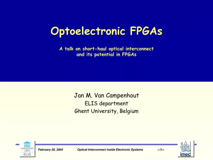
Optoelectronic FPGAs A talk on short-haul optical interconnect and its potential in FPGAs. Jan M. Van Campenhout ELIS department Ghent University, Belgium. Outline. Short-haul optical interconnect and its goals Interconnect contexts and their significance for OI

E N D
Optoelectronic FPGAsA talk on short-haul optical interconnect and its potential in FPGAs Jan M. Van Campenhout ELIS department Ghent University, Belgium Optical Interconnect inside Electronic Systems
Outline • Short-haul optical interconnect and its goals • Interconnect contexts and their significance for OI • Issues in effective parallel, short-haul interconnect • An experiment from the past: the OIIC optoelectronic FPGA • Optical interconnect and FPGAs: the future Optical Interconnect inside Electronic Systems
Short-haul optical interconnect and its goals Why would we use meter-range optical interconnect as a substitute for electrical interconnect? What are the precise requirements for the optical interconnect? Is it bandwidth? Is it power dissipation? Is it physical density? Is it reduced skew? Is it physical distance? … • Requirements very often are conflicting and context dependent • Actual interconnect properties complex result of properties of subcomponents Optical Interconnect inside Electronic Systems
The requirement side the interconnect context Combined set of system context parameters define coherent set of boundary conditions for interconnect at link level Important parameters: • Behavioral: • Clocking behavior (Synchronous, Mesochronous, Plesiochronous, Asynchronous) with related parameters (latency, skew, …) • Power dissipation; speed-power product • Aggregate bit rate; error rate • Topological: point-to-point vs. broadcast or bus; parallelism • Metrical: distance covered; required density Optical Interconnect inside Electronic Systems
The interconnect space:examples Behavior globally synchr locally synchr Processor L2-to-Main Memory link asynch single, point-to-point Clock distribution tree multiple, point-to-point intrachip Parallel Datacom link single, multipoint MCM multiple, multipoint Boardlevel Serial network link Backplane Cabinet Lan Wan Topology Metrics Short-haul Optical Evolution Optical Interconnect inside Electronic Systems
Telecom is not Datacom Link is not Short-haul Interconnect Optical Interconnect inside Electronic Systems
Some existing datacom links (< 300 m typ)are thriving Optical Interconnect inside Electronic Systems
Short-haul interconnect poses additional requirements and issues • Parallelism of interconnect much larger: 8 x 8 up to 16 x 16 • Alignment accuracy of +/- 10 mm across entire array; must be compatible with electrical assembly (BGA) • Connectorisation and manufacturing of optical pathway (2-D ribbons, embedding,…) • Uniformity of optical devices in large arrays • Embedding of link into functional CMOS • Hybridisation problems; through-substrate operation (wave length, thinning) • Required package hermeticity and connectorisation to chip level • More complicated heat evacuation requirements • Strong electrical environment noise aggressive to receivers • Use of plastic materials in view of mechanical properties (bending) • Compatibility of plastic parts with reflow temperatures during assembly • Handling of very flexible fibre in production process Optical Interconnect inside Electronic Systems
The OIIC system demonstrator: an opto-electronic FPGA (1998) • Use optical interconnects to realize 3-D extension of the electrical on-chip interconnect fabric • offers a highly compact and densely interconnected multi-FPGA system • should provide an essentially 3-D routing environment, leading to shorter average wire lengths, hence faster systems • should provide an increased routability of complex designs • should allow high bit rates over many parallel channels OIIC (Optically Interconnected Integrated Circuits, EP 22641) -- Sep 1996 - Jan 2001 Optical Interconnect inside Electronic Systems
Physical view: from 3-D back to the planeUnfolding allowed by flexible POF optical pathway 3-D setup could be realized with free-space optics and transparent substrates Unfolding the 3-D geometry using flexible ribbon-based interconnect allows the use of non-transparent Si substrates Optical Interconnect inside Electronic Systems
Probing the effect of massive short-haul optical interconnects in FPGAs Perform a large number of partitioning experiments* • Onto a variety of architectures • Using public-domain benchmarks (ISPD98) Estimate maximum clock frequency of synchronous circuits * J.Dambre,H.Van Marck,and J.Van Campenhout, Proc . PI ’99 Optical Interconnect inside Electronic Systems
Result: increase in operation speed possible with low-latency optical interconnect 3-D interconnect leads to sizeable speed gains provided link latency small enough Critical value: better than electrical interchip interconnect Gains biggest for large complex circuits Optical Interconnect inside Electronic Systems
Concrete realization: OE FPGA module Photo detector arrays LED or VCSEL arrays 4 8 or 8 8 arrays flip chip mounted 2D array 16 8 fibers of custom-made 125-mm diameter PMMA POF with 90º termination block on precision spacers Optical Interconnect inside Electronic Systems
The OIIC system demonstrator: board view Optical Interconnect inside Electronic Systems
OIIC lesson 1: Technology is essentially available The FPGA demonstrator has been built and thoroughly tested Essential technology is available* and has been transferred to industry: • Arrays (8 x 8) of optical devices can be produced with good yield and uniformity • Hybridization through flip-chip mounting of optical arrays feasible with good bonding yield • Driver and receiver circuits compatible with standard CMOS processes available; Gigabit rates pose no problem • Use of multimode, POF-based optical pathways allows relatively simple passive alignment techniques and easy termination and connectorization Increased pickup by industry is essential to provide reliable sources *H. Neefs (ed), Achievements 1996-2000, Advanced Research Initiative in Microelectronics, European commission, 2000 Optical Interconnect inside Electronic Systems
OIIC lesson 2: Pathways need much more attention Ribbon-like optical pathway OK for inter-cabinet interconnects, not for board-level inter-chip interconnects Need integrated solutions for board-level application (MCM, PCB, Backplane) • Integration can be build-up or in-board solution • Special attention required by • Thermal compatibility of pathway materials with soldering • Hermeticity requirements of electrical components • Reliable and low-cost passive alignment • Connectorization and 90-degree bends for two-dimensional arrays of fibers But: significant progress being made by various research teams (-> IO) Optical Interconnect inside Electronic Systems
OIIC lesson 3: Speed-power performance compares favorably with electrical interconnects *U. Vogel, R. Jahne, S. Ulbricht, G. Bunk, Essirc2000 Optical Interconnect inside Electronic Systems
OIIC lesson 4: Use at logic level only in special cases Residual interconnect latency comparable to electrical I/O pins Is too much for use at logic level in ASIC designs; could be tolerable in special cases (with latency tolerance): • The case just studied: FPGAs • Unidirectional pipelines • Multi-rate synchronous systems Inter-chip optical interconnects should preferably be used at R/T level or higher, the same way high-performance electrical links are used: • as multi-fiber interconnects sharing the same (embedded) clock • With optimized receivers, taking the presence of clock into account Optical Interconnect inside Electronic Systems
Modern FPGA trends Underlying OIIC assumptions of FPGA structure no longer entirely valid: • Modern FPGAs have much more complex internal structure (memory blocks, carry chains, R/T-level primitives, embedded cores) • SoC strives towards single-FPGA solutions, avoiding logic-level interconnect of many FPGAs However: • Basic operation frequency, pincount & bandwidth req’s are growing fast • Growing demand for high-speed interconnect into application environment as well as inter-FPGA Optical Interconnect inside Electronic Systems
Current SERDES backplane evolution and FPGAs Serializing interchip interconnect attempts to solve electrical backplane interconnect problems: • Trades parallelism and pin count for bit rate • Eliminates cross-talk & skew problems of parallel interconnects • Pre-emphasis technique allows for high bandwidth on copper Examples of standards: • 10G Attachment Unit Interface (4 x 3.125 Gb/s) • 3GIO (PCI Express) (up to 80 x 2.5 Gb/s) • Serial Rapid I/O (up to 3.125 Gb/s) • Infiniband (12 x 2.5 Gb/s) High-speed serial I/O offered by most high-end FPGA manufacturers: • Xilinx Rocket IO (on the Virtex II Pro series) • Altera Serialite (on the Stratix GX family) • Lattice SerDes (ORCA series) Optical Interconnect inside Electronic Systems
Current SERDES backplane evolution and FPGAs (2) However: • Overall latency due to serialization my be an issue • Copper length at high bit rates limited: what about copper intercabinet links at > 5 Gb/s? • Power dissipation is going up fast (800 mW @10 Gb/s = 80 pJ) • What about scalability (to higher # of links, higher rates?): extreme burden on PCB layout Short-haul optical interconnect offers elegant solution: • Can provide highly dense, low-latency interconnect down to the chip level without stringent distance-bandwidth limitation • Scalability perspectives are excellent (even using parallel interconnects: skew problems much less critical) • Power dissipation perspective very good Optical Interconnect inside Electronic Systems
Lattice SERDES road map 100 Gbps FPSC - High Performance FPGAs with Embedded Interface cores and SERDES 32Channels x 3.7Gbps Lattice offers the most options for programmable SERDES… ORCA Series 5 30 Gbps 8 Channels x 4.25Gbps ispXPGA - High Performance FPGAs with Instant-On and SERDES ORCA ORT82G5 8 Channels x 2.7Gbps GDX2 - Programmable Digital Interconnects and SERDES Aggregate Bandwidth per Device 20 Channels x 850Mbps ORCA ORSO82G5 ispXPGA 1200 16 Channels x 850Mbps 15 Gbps ORCA ORSPI4 12 Channels x 850Mbps GDX2-256 8 Channels x 850Mbps 8 Channels x 850Mbps 8 Channels x 850Mbps ispXPGA 500 ispXPGA 200 ORCA ORT8850 4 Channels x 850Mbps 4 Channels x 850Mbps GDX2-128 ispXPGA 125 GDX2-64 GDX2 ispXPGA FPSC Courtesy Lattice Semiconductor 2003 Optical Interconnect inside Electronic Systems
Conclusions Short-haul parallel optical interconnect with direct chip access makes sense in high-speed FPGA I/O • Provides scalability: can combine high link counts with high bit rate without excessive power requirements or PCB escape problems • Allows to eliminate one level from the interconnect hierarchy: inter chip = inter board = inter cabinet • Base technology essentially available Optical Interconnect inside Electronic Systems