Download
1 / 41
410 likes | 529 Views
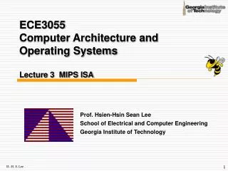
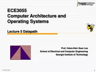
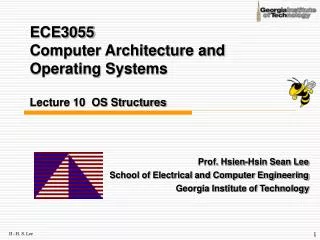
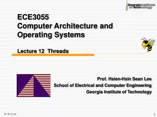
ECE3055 Computer Architecture and Operating Systems Lecture 6 Multi-cycle Datapath. Prof. Hsien-Hsin Sean Lee School of Electrical and Computer Engineering Georgia Institute of Technology. Multi-cycle Approach. Single-cycle design

E N D
ECE3055 Computer Architecture and Operating SystemsLecture 6 Multi-cycle Datapath Prof. Hsien-Hsin Sean Lee School of Electrical and Computer Engineering Georgia Institute of Technology
Multi-cycle Approach • Single-cycle design • Clock period is limited by the “worst case instruction timing” (which instructions?) • Violate Amdahl’s Law: Make the common case faster • Require duplication of some functional units such as adders for PC generation and an ALU for arithmetic • Multi-cycle design • We will be reusing functional units and memory • ALU used to compute address and to increment PC • Memory used for instruction and data • Our control signals will not be determined solely by instruction • e.g., what should the ALU do for a “subtract” instruction? • We’ll use a finite state machine for control • State elements needed for transient data produced by “the same instruction”
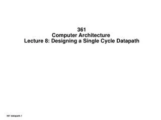
I n s t r u c t i o n r e g i s t e r D a t a P C A d d r e s s A R e g i s t e r # I n s t r u c t i o n A L U A L U O u t M e m o r y R e g i s t e r s o r d a t a R e g i s t e r # M e m o r y d a t a B D a t a r e g i s t e r R e g i s t e r # Multi-Cycle Datapath
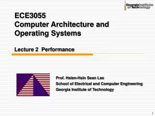
P C 0 0 I n s t r u c t i o n R e a d M M [ 2 5 – 2 1 ] r e g i s t e r 1 A d d r e s s u u x x R e a d A I n s t r u c t i o n R e a d Z e r o M e m o r y 1 d a t a 1 1 [ 2 0 – 1 6 ] r e g i s t e r 2 A L U A L U A L U O u t 0 M e m D a t a R e g i s t e r s r e s u l t I n s t r u c t i o n W r i t e M R e a d [ 1 5 – 0 ] r e g i s t e r B u 0 d a t a 2 I n s t r u c t i o n W r i t e I/D x [ 1 5 – 1 1 ] M I n s t r u c t i o n 4 1 W r i t e d a t a 1 u r e g i s t e r d a t a 2 x 0 I n s t r u c t i o n 3 [ 1 5 – 0 ] M u x M e m o r y 1 1 6 3 2 d a t a S h i f t S i g n r e g i s t e r l e f t 2 e x t e n d Multi-Cycle Approach • Break up the instructions into steps, each step takes a cycle • balance the amount of work to be done • restrict each cycle to use only one major functional unit • At the end of a cycle • store values for use in later cycles (easiest thing to do) • introduce additional “internal” registers
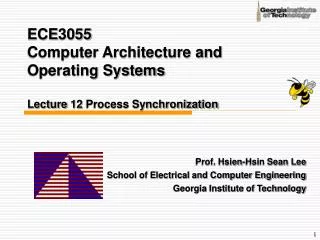
I o r D M e m R e a d M e m W r i t e I R W r i t e R e g D s t R e g W r i t e A L U S r c A P C 0 0 I n s t r u c t i o n R e a d M M [ 2 5 – 2 1 ] r e g i s t e r 1 A d d r e s s u u x R e a d x A I n s t r u c t i o n R e a d Z e r o d a t a 1 M e m o r y 1 1 [ 2 0 – 1 6 ] r e g i s t e r 2 A L U A L U A L U O u t 0 M e m D a t a R e g i s t e r s r e s u l t I n s t r u c t i o n W r i t e R e a d M B [ 1 5 – 0 ] r e g i s t e r d a t a 2 0 u I n s t r u c t i o n W r i t e x M [ 1 5 – 1 1 ] I n s t r u c t i o n 4 1 W r i t e d a t a 1 u r e g i s t e r d a t a 2 x 0 I n s t r u c t i o n 3 [ 1 5 – 0 ] M u x M e m o r y 1 1 6 3 2 d a t a A L U S h i f t S i g n r e g i s t e r c o n t r o l l e f t 2 e x t e n d I n s t r u c t i o n [ 5 – 0 ] M e m t o R e g A L U S r c B A L U O p Control Signals of a Multi-Cycle Datapath
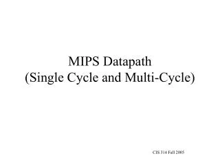
P C W r i t e C o n d P C S o u r c e P C W r i t e A L U O p O u t p u t s I o r D A L U S r c B M e m R e a d A L U S r c A C o n t r o l M e m W r i t e R e g W r i t e M e m t o R e g O p R e g D s t I R W r i t e [ 5 – 0 ] 0 M 1 u J u m p 2 6 2 8 x I n s t r u c t i o n [ 2 5 – 0 ] a d d r e s s [ 3 1 - 0 ] S h i f t 2 l e f t 2 I n s t r u c t i o n [ 3 1 - 2 6 ] P C [ 3 1 - 2 8 ] P C 0 0 I n s t r u c t i o n R e a d M M [ 2 5 – 2 1 ] r e g i s t e r 1 u A d d r e s s u x x R e a d A I n s t r u c t i o n R e a d Z e r o M e m o r y 1 d a t a 1 1 [ 2 0 – 1 6 ] r e g i s t e r 2 A L U A L U A L U O u t 0 M e m D a t a R e g i s t e r s r e s u l t I n s t r u c t i o n W r i t e M R e a d B [ 1 5 – 0 ] r e g i s t e r u 0 I n s t r u c t i o n d a t a 2 W r i t e x [ 1 5 – 1 1 ] M I n s t r u c t i o n 4 1 W r i t e d a t a 1 u r e g i s t e r d a t a 2 x 0 I n s t r u c t i o n 3 [ 1 5 – 0 ] M u x M e m o r y 1 1 6 3 2 d a t a A L U S h i f t S i g n r e g i s t e r c o n t r o l l e f t 2 e x t e n d I n s t r u c t i o n [ 5 – 0 ] Complete Control Lines
Five Execution Steps • Instruction Fetch (IF) • Instruction Decode and Register Fetch (ID) • Execution, Memory Address Computation, or Branch Completion (EX) • Memory Access or R-type instruction completion (MEM) • Write-back step (WB)
Instruction Fetch (IF) • Use PC to get instruction and put it in the Instruction Register. • Increment the PC by 4 and put the result back in the PC. • Can be described succinctly using RTL "Register-Transfer Language"IR = Memory[PC]; PC = PC + 4;Can we figure out the values of the control signals? • IR = Memory[PC];MemRead=1; IRWrite=1; IorD=0; • PC = PC + 4; ALUSrcA=0; ALUSrcB=01; ALUOp=00 (add); PCSource=00; PCWrite=1
P C W r i t e C o n d P C S o u r c e P C W r i t e A L U O p O u t p u t s I o r D A L U S r c B M e m R e a d A L U S r c A C o n t r o l M e m W r i t e R e g W r i t e M e m t o R e g O p R e g D s t I R W r i t e [ 5 – 0 ] 0 M 1 u J u m p 2 6 2 8 x I n s t r u c t i o n [ 2 5 – 0 ] a d d r e s s [ 3 1 - 0 ] S h i f t 2 l e f t 2 I n s t r u c t i o n [ 3 1 - 2 6 ] P C [ 3 1 - 2 8 ] P C 0 0 I n s t r u c t i o n R e a d M M [ 2 5 – 2 1 ] r e g i s t e r 1 u A d d r e s s u x x R e a d A I n s t r u c t i o n R e a d Z e r o M e m o r y 1 d a t a 1 1 [ 2 0 – 1 6 ] r e g i s t e r 2 A L U A L U A L U O u t 0 M e m D a t a R e g i s t e r s r e s u l t I n s t r u c t i o n W r i t e M R e a d B [ 1 5 – 0 ] r e g i s t e r u 0 I n s t r u c t i o n d a t a 2 W r i t e x [ 1 5 – 1 1 ] M I n s t r u c t i o n 4 1 W r i t e d a t a 1 u r e g i s t e r d a t a 2 x 0 I n s t r u c t i o n 3 [ 1 5 – 0 ] M u x M e m o r y 1 1 6 3 2 d a t a A L U S h i f t S i g n r e g i s t e r c o n t r o l l e f t 2 e x t e n d I n s t r u c t i o n [ 5 – 0 ] Instruction Fetch Control IR = Memory[PC]; PC+=4
Instruction Decode and Register Fetch (ID) • Still do not have any idea what instruction it is. • Read registers rs and rt in case we need them • Compute the branch address (used in next cycle in case the instruction is a branch) • RTL:A = Reg[IR[25-21]]; B = Reg[IR[20-16]]; ALUOut = PC + (sign-extend(IR[15-0]) << 2); ALUSrcA = 0; ALUSrcB = 11; ALUOp = 00 (add); (for branch target)
P C W r i t e C o n d P C S o u r c e P C W r i t e A L U O p O u t p u t s I o r D A L U S r c B M e m R e a d A L U S r c A C o n t r o l M e m W r i t e R e g W r i t e M e m t o R e g O p R e g D s t I R W r i t e [ 5 – 0 ] 0 M 1 u J u m p 2 6 2 8 x I n s t r u c t i o n [ 2 5 – 0 ] a d d r e s s [ 3 1 - 0 ] S h i f t 2 l e f t 2 I n s t r u c t i o n [ 3 1 - 2 6 ] P C [ 3 1 - 2 8 ] P C 0 0 I n s t r u c t i o n R e a d M M [ 2 5 – 2 1 ] r e g i s t e r 1 u A d d r e s s u x x R e a d A I n s t r u c t i o n R e a d Z e r o M e m o r y 1 d a t a 1 1 [ 2 0 – 1 6 ] r e g i s t e r 2 A L U A L U A L U O u t 0 M e m D a t a R e g i s t e r s r e s u l t I n s t r u c t i o n W r i t e M R e a d B [ 1 5 – 0 ] r e g i s t e r u 0 I n s t r u c t i o n d a t a 2 W r i t e x [ 1 5 – 1 1 ] M I n s t r u c t i o n 4 1 W r i t e d a t a 1 u r e g i s t e r d a t a 2 x 0 I n s t r u c t i o n 3 [ 1 5 – 0 ] M u x M e m o r y 1 1 6 3 2 d a t a A L U S h i f t S i g n r e g i s t e r c o n t r o l l e f t 2 e x t e n d I n s t r u c t i o n [ 5 – 0 ] ID Stage: Assign A and B; Calculate Branch Address
Execute, memory or branch (EX: instruction dependent) • The first cycle, the operation is determined by the instruction class • ALU is performing one of the following functions, based on instruction type • Memory Reference: ALUOut = A + sign-extend(IR[15-0]);ALUSrcA=1; ALUSrcB=10; ALUop=00 (add) • R-type: ALUOut = A op B;ALUSrcA=1; ALUSrcB=00; ALUop=10 (funct, inst[5:0], decides op) • Branch: if (A==B) PC = ALUOut; PCSource=01; ALUSrcA=1; ALUSrcB=00; ALUop=01 (sub); PCWriteCond=1; PCWrite=0; • Jump: PC = {PC[31:28] || IR[25:0] || 2‘b00}; PCSource=10; PCWrite=1;
P C W r i t e C o n d P C S o u r c e P C W r i t e A L U O p O u t p u t s I o r D A L U S r c B M e m R e a d A L U S r c A C o n t r o l M e m W r i t e R e g W r i t e M e m t o R e g O p R e g D s t I R W r i t e [ 5 – 0 ] 0 M 1 u J u m p 2 6 2 8 x I n s t r u c t i o n [ 2 5 – 0 ] a d d r e s s [ 3 1 - 0 ] S h i f t 2 l e f t 2 I n s t r u c t i o n [ 3 1 - 2 6 ] P C [ 3 1 - 2 8 ] P C 0 0 I n s t r u c t i o n R e a d M M [ 2 5 – 2 1 ] r e g i s t e r 1 u A d d r e s s u x x R e a d A I n s t r u c t i o n R e a d Z e r o M e m o r y 1 d a t a 1 1 [ 2 0 – 1 6 ] r e g i s t e r 2 A L U A L U A L U O u t 0 M e m D a t a R e g i s t e r s r e s u l t I n s t r u c t i o n W r i t e M R e a d B [ 1 5 – 0 ] r e g i s t e r u 0 I n s t r u c t i o n d a t a 2 W r i t e x [ 1 5 – 1 1 ] M I n s t r u c t i o n 4 1 W r i t e d a t a 1 u r e g i s t e r d a t a 2 x 0 I n s t r u c t i o n 3 [ 1 5 – 0 ] M u x M e m o r y 1 1 6 3 2 d a t a A L U S h i f t S i g n r e g i s t e r c o n t r o l l e f t 2 e x t e n d I n s t r u c t i o n [ 5 – 0 ] Execute: Memory TypeALUOut = A + offset (address)
P C W r i t e C o n d P C S o u r c e P C W r i t e A L U O p O u t p u t s I o r D A L U S r c B M e m R e a d A L U S r c A C o n t r o l M e m W r i t e R e g W r i t e M e m t o R e g O p R e g D s t I R W r i t e [ 5 – 0 ] 0 M 1 u J u m p 2 6 2 8 x I n s t r u c t i o n [ 2 5 – 0 ] a d d r e s s [ 3 1 - 0 ] S h i f t 2 l e f t 2 I n s t r u c t i o n [ 3 1 - 2 6 ] P C [ 3 1 - 2 8 ] P C 0 0 I n s t r u c t i o n R e a d M M [ 2 5 – 2 1 ] r e g i s t e r 1 u A d d r e s s u x x R e a d A I n s t r u c t i o n R e a d Z e r o M e m o r y 1 d a t a 1 1 [ 2 0 – 1 6 ] r e g i s t e r 2 A L U A L U A L U O u t 0 M e m D a t a R e g i s t e r s r e s u l t I n s t r u c t i o n W r i t e M R e a d B [ 1 5 – 0 ] r e g i s t e r u 0 I n s t r u c t i o n d a t a 2 W r i t e x [ 1 5 – 1 1 ] M I n s t r u c t i o n 4 1 W r i t e d a t a 1 u r e g i s t e r d a t a 2 x 0 I n s t r u c t i o n 3 [ 1 5 – 0 ] M u x M e m o r y 1 1 6 3 2 d a t a A L U S h i f t S i g n r e g i s t e r c o n t r o l l e f t 2 e x t e n d I n s t r u c t i o n [ 5 – 0 ] Execute: R- TypeALUOut = A op B
P C W r i t e C o n d P C S o u r c e P C W r i t e A L U O p O u t p u t s I o r D A L U S r c B M e m R e a d A L U S r c A C o n t r o l M e m W r i t e R e g W r i t e M e m t o R e g O p R e g D s t I R W r i t e [ 5 – 0 ] 0 M 1 u J u m p 2 6 2 8 x I n s t r u c t i o n [ 2 5 – 0 ] a d d r e s s [ 3 1 - 0 ] S h i f t 2 l e f t 2 I n s t r u c t i o n [ 3 1 - 2 6 ] P C [ 3 1 - 2 8 ] P C 0 0 I n s t r u c t i o n R e a d M M [ 2 5 – 2 1 ] r e g i s t e r 1 u A d d r e s s u x x R e a d A I n s t r u c t i o n R e a d Z e r o M e m o r y 1 d a t a 1 1 [ 2 0 – 1 6 ] r e g i s t e r 2 A L U A L U A L U O u t 0 M e m D a t a R e g i s t e r s r e s u l t I n s t r u c t i o n W r i t e M R e a d B [ 1 5 – 0 ] r e g i s t e r u 0 I n s t r u c t i o n d a t a 2 W r i t e x [ 1 5 – 1 1 ] M I n s t r u c t i o n 4 1 W r i t e d a t a 1 u r e g i s t e r d a t a 2 x 0 I n s t r u c t i o n 3 [ 1 5 – 0 ] M u x M e m o r y 1 1 6 3 2 d a t a A L U S h i f t S i g n r e g i s t e r c o n t r o l l e f t 2 e x t e n d I n s t r u c t i o n [ 5 – 0 ] Execute: Branch Typeif (A==B) PC=ALUOut
P C W r i t e C o n d P C S o u r c e P C W r i t e A L U O p O u t p u t s I o r D A L U S r c B M e m R e a d A L U S r c A C o n t r o l M e m W r i t e R e g W r i t e M e m t o R e g O p R e g D s t I R W r i t e [ 5 – 0 ] 0 M 1 u J u m p 2 6 2 8 x I n s t r u c t i o n [ 2 5 – 0 ] a d d r e s s [ 3 1 - 0 ] S h i f t 2 l e f t 2 I n s t r u c t i o n [ 3 1 - 2 6 ] P C [ 3 1 - 2 8 ] P C 0 0 I n s t r u c t i o n R e a d M M [ 2 5 – 2 1 ] r e g i s t e r 1 u A d d r e s s u x x R e a d A I n s t r u c t i o n R e a d Z e r o M e m o r y 1 d a t a 1 1 [ 2 0 – 1 6 ] r e g i s t e r 2 A L U A L U A L U O u t 0 M e m D a t a R e g i s t e r s r e s u l t I n s t r u c t i o n W r i t e M R e a d B [ 1 5 – 0 ] r e g i s t e r u 0 I n s t r u c t i o n d a t a 2 W r i t e x [ 1 5 – 1 1 ] M I n s t r u c t i o n 4 1 W r i t e d a t a 1 u r e g i s t e r d a t a 2 x 0 I n s t r u c t i o n 3 [ 1 5 – 0 ] M u x M e m o r y 1 1 6 3 2 d a t a A L U S h i f t S i g n r e g i s t e r c o n t r o l l e f t 2 e x t e n d I n s t r u c t i o n [ 5 – 0 ] Execute: Jump Type (New PC)
Memory Access or R-Type • Loads and stores access memoryMDR = Memory[ALUOut];IorD=1; MemRead=1; or Memory[ALUOut] = B;IorD=1; MemWrite=1 • R-type instructions finishReg[IR[15-11]] = ALUOut;RegDst=1; MemtoReg=0; RegWrite =1
P C W r i t e C o n d P C S o u r c e P C W r i t e A L U O p O u t p u t s I o r D A L U S r c B M e m R e a d A L U S r c A C o n t r o l M e m W r i t e R e g W r i t e M e m t o R e g O p R e g D s t I R W r i t e [ 5 – 0 ] 0 M 1 u J u m p 2 6 2 8 x I n s t r u c t i o n [ 2 5 – 0 ] a d d r e s s [ 3 1 - 0 ] S h i f t 2 l e f t 2 I n s t r u c t i o n [ 3 1 - 2 6 ] P C [ 3 1 - 2 8 ] P C 0 0 I n s t r u c t i o n R e a d M M [ 2 5 – 2 1 ] r e g i s t e r 1 u A d d r e s s u x x R e a d A I n s t r u c t i o n R e a d Z e r o M e m o r y 1 d a t a 1 1 [ 2 0 – 1 6 ] r e g i s t e r 2 A L U A L U A L U O u t 0 M e m D a t a R e g i s t e r s r e s u l t I n s t r u c t i o n W r i t e M R e a d B [ 1 5 – 0 ] r e g i s t e r u 0 I n s t r u c t i o n d a t a 2 W r i t e x [ 1 5 – 1 1 ] M I n s t r u c t i o n 4 1 W r i t e d a t a 1 u r e g i s t e r d a t a 2 x 0 I n s t r u c t i o n 3 [ 1 5 – 0 ] M u x M e m o r y 1 1 6 3 2 d a t a A L U S h i f t S i g n r e g i s t e r c o n t r o l l e f t 2 e x t e n d I n s t r u c t i o n [ 5 – 0 ] MEM: Load
P C W r i t e C o n d P C S o u r c e P C W r i t e A L U O p O u t p u t s I o r D A L U S r c B M e m R e a d A L U S r c A C o n t r o l M e m W r i t e R e g W r i t e M e m t o R e g O p R e g D s t I R W r i t e [ 5 – 0 ] 0 M 1 u J u m p 2 6 2 8 x I n s t r u c t i o n [ 2 5 – 0 ] a d d r e s s [ 3 1 - 0 ] S h i f t 2 l e f t 2 I n s t r u c t i o n [ 3 1 - 2 6 ] P C [ 3 1 - 2 8 ] P C 0 0 I n s t r u c t i o n R e a d M M [ 2 5 – 2 1 ] r e g i s t e r 1 u A d d r e s s u x x R e a d A I n s t r u c t i o n R e a d Z e r o M e m o r y 1 d a t a 1 1 [ 2 0 – 1 6 ] r e g i s t e r 2 A L U A L U A L U O u t 0 M e m D a t a R e g i s t e r s r e s u l t I n s t r u c t i o n W r i t e M R e a d B [ 1 5 – 0 ] r e g i s t e r u 0 I n s t r u c t i o n d a t a 2 W r i t e x [ 1 5 – 1 1 ] M I n s t r u c t i o n 4 1 W r i t e d a t a 1 u r e g i s t e r d a t a 2 x 0 I n s t r u c t i o n 3 [ 1 5 – 0 ] M u x M e m o r y 1 1 6 3 2 d a t a A L U S h i f t S i g n r e g i s t e r c o n t r o l l e f t 2 e x t e n d I n s t r u c t i o n [ 5 – 0 ] MEM: Store
P C W r i t e C o n d P C S o u r c e P C W r i t e A L U O p O u t p u t s I o r D A L U S r c B M e m R e a d A L U S r c A C o n t r o l M e m W r i t e R e g W r i t e M e m t o R e g O p R e g D s t I R W r i t e [ 5 – 0 ] 0 M 1 u J u m p 2 6 2 8 x I n s t r u c t i o n [ 2 5 – 0 ] a d d r e s s [ 3 1 - 0 ] S h i f t 2 l e f t 2 I n s t r u c t i o n [ 3 1 - 2 6 ] P C [ 3 1 - 2 8 ] P C 0 0 I n s t r u c t i o n R e a d M M [ 2 5 – 2 1 ] r e g i s t e r 1 u A d d r e s s u x x R e a d A I n s t r u c t i o n R e a d Z e r o M e m o r y 1 d a t a 1 1 [ 2 0 – 1 6 ] r e g i s t e r 2 A L U A L U A L U O u t 0 M e m D a t a R e g i s t e r s r e s u l t I n s t r u c t i o n W r i t e M R e a d B [ 1 5 – 0 ] r e g i s t e r u 0 I n s t r u c t i o n d a t a 2 W r i t e x [ 1 5 – 1 1 ] M I n s t r u c t i o n 4 1 W r i t e d a t a 1 u r e g i s t e r d a t a 2 x 0 I n s t r u c t i o n 3 [ 1 5 – 0 ] M u x M e m o r y 1 1 6 3 2 d a t a A L U S h i f t S i g n r e g i s t e r c o n t r o l l e f t 2 e x t e n d I n s t r u c t i o n [ 5 – 0 ] MEM: R-Type Completion
Write-back for load operation • Reg[IR[20-16]]= MDR;MemtoReg=1; RegWrite=1; RegDst=0; What about all the other instructions?
P C W r i t e C o n d P C S o u r c e P C W r i t e A L U O p O u t p u t s I o r D A L U S r c B M e m R e a d A L U S r c A C o n t r o l M e m W r i t e R e g W r i t e M e m t o R e g O p R e g D s t I R W r i t e [ 5 – 0 ] 0 M 1 u J u m p 2 6 2 8 x I n s t r u c t i o n [ 2 5 – 0 ] a d d r e s s [ 3 1 - 0 ] S h i f t 2 l e f t 2 I n s t r u c t i o n [ 3 1 - 2 6 ] P C [ 3 1 - 2 8 ] P C 0 0 I n s t r u c t i o n R e a d M M [ 2 5 – 2 1 ] r e g i s t e r 1 u A d d r e s s u x x R e a d A I n s t r u c t i o n R e a d Z e r o M e m o r y 1 d a t a 1 1 [ 2 0 – 1 6 ] r e g i s t e r 2 A L U A L U A L U O u t 0 M e m D a t a R e g i s t e r s r e s u l t I n s t r u c t i o n W r i t e M R e a d B [ 1 5 – 0 ] r e g i s t e r u 0 I n s t r u c t i o n d a t a 2 W r i t e x [ 1 5 – 1 1 ] M I n s t r u c t i o n 4 1 W r i t e d a t a 1 u r e g i s t e r d a t a 2 x 0 I n s t r u c t i o n 3 [ 1 5 – 0 ] M u x M e m o r y 1 1 6 3 2 d a t a A L U S h i f t S i g n r e g i s t e r c o n t r o l l e f t 2 e x t e n d I n s t r u c t i o n [ 5 – 0 ] WB for Load
Simple Questions • How many cycles will it take to execute this code? lw $t2, 0($t3) lw $t3, 4($t3) beq $t2, $t3, Label #assume not add $t5, $t2, $t3 sw $t5, 8($t3)Label: ... • What is going on during the 8th cycle of execution? • In what cycle does the actual addition of $t2 and $t3 takes place?
Implementing the Control • Value of control signals is dependent upon: • what instruction is being executed • which step is being performed • Use the information we’ve accumulated to specify a finite state machine • specify the finite state machine graphically, or • use microprogramming • Implementation can be derived from specification
I n s t r u c t i o n d e c o d e / I n s t r u c t i o n f e t c h r e g i s t e r f e t c h M e m R e a d A L U S r c A = 0 I o r D = 0 A L U S r c A = 0 I R W r i t e A L U S r c B = 1 1 A L U S r c B = 0 1 A L U O p = 0 0 A L U O p = 0 0 P C W r i t e P C S o u r c e = 0 0 R = p O ( ) ' W M e m o r y a d d r e s s S ' B r a n c h = J u m p p O c o m p u t a t i o n ( r o E x e c u t i o n c o m p l e t i o n ) c o m p l e t i o n ' W L ' = p O ( A L U S r c A = 1 A L U S r c A = 1 A L U S r c B = 0 0 A L U S r c A = 1 P C W r i t e A L U S r c B = 1 0 A L U O p = 0 1 A L U S r c B = 0 0 P C S o u r c e = 1 0 A L U O p = 0 0 P C W r i t e C o n d A L U O p = 1 0 P C S o u r c e = 0 1 M e m o r y M e m o r y a c c e s s a c c e s s R - t y p e c o m p l e t i o n R e g D s t = 1 M e m R e a d M e m W r i t e R e g W r i t e I o r D = 1 I o r D = 1 M e m t o R e g = 0 W r i t e - b a c k s t e p R e g D s t = 0 R e g W r i t e M e m t o R e g = 1 Graphical Specification of FSM 0 1 S t a r t ) ) ' e Q p ) y t ' E - J B ' ' = = p p O O ( ( 2 6 8 9 ( O ) p ' = W ' S L ' W ' = ) p O ( 3 5 7 4
Finite State Machine for Control • Implementation: P C W r i t e P C W r i t e C o n d I o r D M e m R e a d Control Logic M e m W r i t e I R W r i t e M e m t o R e g P C S o u r c e A L U O p Outputs A L U S r c B A L U S r c A R e g W r i t e R e g D s t N S 3 N S 2 Inputs N S 1 N S 0 4 3 2 1 0 5 p p p p p p 3 2 1 0 O O O O O O S S S S I n s t r u c t i o n r e g i s t e r S t a t e r e g i s t e r o p c o d e f i e l d
O p 5 O p 4 O p 3 O p 2 O p 1 O p 0 S 3 S 2 S 1 S 0 P C W r i t e P C W r i t e C o n d I o r D M e m R e a d M e m W r i t e I R W r i t e M e m t o R e g P C S o u r c e 1 P C S o u r c e 0 A L U O p 1 A L U O p 0 A L U S r c B 1 A L U S r c B 0 A L U S r c A R e g W r i t e R e g D s t N S 3 N S 2 N S 1 N S 0 PLA Implementation
Other Implementations • ROM • Microprogramming • Break instruction into several micro-instructions • Execute micro-instructions to generate signals • Suitable for large number of opcodes and complex control signals
m n ROM Implementation • ROM = "Read Only Memory" • values of memory locations are fixed ahead of time • A ROM can be used to implement a truth table • if the address is m-bits, we can address 2m entries in the ROM. • our outputs are the bits of data that the address points to.m is the "heigth", and n is the "width" 0 0 0 0 0 1 1 0 0 1 1 1 0 0 0 1 0 1 1 0 0 0 1 1 1 0 0 0 1 0 0 0 0 0 0 1 0 1 0 0 0 1 1 1 0 0 1 1 0 1 1 1 0 1 1 1
ROM Implementation • How many inputs are there? 6 bits for opcode, 4 bits for state = 10 address lines (i.e., 210 = 1024 different addresses) • How many outputs are there? 16 datapath-control outputs, 4 state bits = 20 outputs • ROM is 210 x 20 = 20K bits (and a rather unusual size) • Rather wasteful, since for lots of the entries, the outputs are the same — i.e., opcode is often ignored
ROM vs. PLA • Break up the table into two parts — 4 state bits tell you the 16 outputs, 24 x 16 bits of ROM — 10 bits tell you the 4 next state bits, 210 x 4 bits of ROM — Total: 4.3K bits of ROM • PLA is much smaller — can share product terms — only need entries that produce an active output — can take into account don't cares • Size is (#inputs ´ #product-terms) + (#outputs ´ #product-terms) For this example = (10x17)+(20x17) = 460 PLA cells • PLA cells usually about the size of a ROM cell (slightly bigger)
Another Implementation Style • Complex instructions: the "next state" is often current state + 1 P C W r i t e C o n t r o l u n i t P C W r i t e C o n d I o r D M e m R e a d P L A o r R O M M e m W r i t e I R W r i t e B W r i t e M e m t o R e g O u t p u t s P C S o u r c e A L U O p A L U S r c B A L U S r c A R e g W r i t e R e g D s t A d d r C t l I n p u t 1 S t a t e A d d e r A d d r e s s s e l e c t l o g i c ] 0 – 5 [ p O I n s t r u c t i o n r e g i s t e r o p c o d e f i e l d
Microprogramming • What are the “microinstructions” ?
Microprogramming • A specification methodology • appropriate if hundreds of opcodes, modes, cycles, etc. • signals specified symbolically using microinstructions • Will two implementations of the same architecture have the same microcode? • What would a microassembler do?
Maximally vs. Minimally Encoded • No encoding: • 1 bit for each datapath operation • faster, requires more memory (logic) • used for Vax 780 — an astonishing 400K of memory! • Lots of encoding: • send the microinstructions through logic to get control signals • uses less memory, slower • Historical context of CISC: • Too much logic to put on a single chip with everything else • Use a ROM (or even RAM) to hold the microcode • It’s easy to add new instructions
Microcode: Trade-offs • Distinction between specification and implementation is sometimes blurred • Specification Advantages: • Easy to design and write • Design architecture and microcode in parallel • Implementation (off-chip ROM) Advantages • Easy to change since values are in memory • Can emulate other architectures • Can make use of internal registers • Implementation Disadvantages, SLOWER now that: • Control is implemented on same chip as processor • ROM is no longer faster than RAM • No need to go back and make changes