Download
1 / 37
560 likes | 1.09k Views
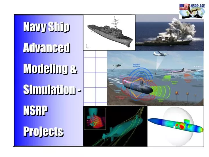
Navy Ship Advanced Modeling & Simulation - NSRP Projects. The Are Two Current NSRP Modeling & Simulation Projects. 1.) NSRP RA 06-01: Improved Methods for Generation of Full-Ship Simulation/Analysis Models 2.) Panel Project: Ship STEP AP Application to Full-Ship Analysis Model Generation.

E N D
Navy Ship Advanced Modeling &Simulation - NSRP Projects
The Are Two Current NSRP Modeling & Simulation Projects 1.) NSRP RA 06-01: Improved Methods for Generation of Full-Ship Simulation/Analysis Models 2.) Panel Project: Ship STEP AP Application to Full-Ship Analysis Model Generation This Project
The Other Project NSRP RA 06-01:Improved Methods for Generation of Full-Ship Simulation/Analysis Models Description: This project is aimed at reducing the cycle time required to develop large scale full ship analysis models for strength, stress, shock, and acoustic simulation and assessment. It responds to Navy Program Executive Officer (PEO) interest in expanding use of modeling and simulation to reduce costs associated with current methods of ship structural testing and analysis. The team will build on the VIRGINIA program’s success in substituting analysis for at-sea live-fire tests, considerable NSRP prior work in design data interoperability, and prior industry investments in ship design tools. The project team will engage with the Navy Full Ship Shock Trial Integrated Process Team (FSST-IPT) to examine cost effective alternatives to replace open-ocean, large-scale shock trials of surface ships. Participants: General Dynamics Electric Boat, Northrop Grumman Ship Systems, Others (TBD)
This NSRP Panel Project Ship STEP AP Application to Full-Ship Analysis Model Generation Lead: General Dynamics – Electric Boat Corporation (EBC) Subcontractors: Northrop Grumman – Ship Systems (NGSS) American Bureau of Shipping (ABS) Product Data Services (PDS) Intergraph Corporation (IC) PDS, Inc.
FSST-IPT Overall Background to Both NSRP Modeling & Simulation Projects
Full-Ship Live-Fire Shock Testing can be Prohibitively Expensive! • Computational Mechanics Transient Simulation is one Viable Alternative • Has Recently Been Accredited for Virginia Class Submarines by PMS450 • (PEOSUB letter 13031 Ser 450/0295 dated 28 Jun 06)
But Its Not Just Shock! Hydrodynamics The Design of Naval Vessels Involves Various High-End Computational Mechanics and Simulation Needs. Acoustics
Commercial Ships Also Have Full-Ship Analysis Requirements Critical Areas in Ultra-Large Container Carriers
Related Modeling & Simulation Efforts We Have Needs for Multi-Disciplinary Modeling & Simulation (M&S) Environments Which Support Varied Requirements Stress Analysis CAD 3D Design Shock Analysis Analysis Context De-Feature, Heal, Mid-Surface Analysis Context Common Abstract Analysis Model Acoustic Analysis Analysis Context
We Need to Consider Multiple Design Stages or Phases (Concept, Preliminary, Detailed, …)
We Need to be More Nimble and Agile in order to Support Various Programs and Ship Systems (Classes) Examples of CAD System Usage DS / CATIA V4 MEC Virginia ClassDS / CATIA V4 AEC CVNX (w/ NNS)DS / CATIA V5 DDG1000 (w/ BIW) AutoCAD SS(G)NPTC / CADDS5 Astute (w/ BAE Vickers)DS / CATIA V5 DDG1000 (w/ BIW) PTC / Dimension III DDG51ShipConstructor USCG DeepwaterIntergraph / ISDP LPD17 EB NGSS We believe an Open, Standards-Based Framework with “Plug & Play” Capability is Required for Efficient Teaming
Overall M&S Background • Need to significantly reduce cost and time for ship modeling, analysis, and simulation • Need to address: • Engineering Labor (Navy spends $5B-$7B per year in all aspects of ship design and engineering). • Live Fire Test and Evaluation (expensive, risky, time consuming, environmental approvals increasingly difficult to obtain)
Designs Developed in CAD environment 3-D Product models Surface Models 2-D Drawings Finite Element Model Models built using Shell and Beam Elements Correct Mass Distribution Required for Dynamic Analysis Limitations of Current Modeling and Simulation Processes Analysis Modeling Space • Generate Analysis Model Geometry from Design Information 80% of Time Too Late to Influence Analysis • Seaway Loads • Weapons Effects 20% of Time
Full Ship Simulation • Simulation models at this scale are generally not automatically created or readily meshed from CAD geometry. • Significant “Touch Labor” is usually required. SFG
ISE NAVY Ships are a Highly Complex Product SSBN 12,000,000 HRS 1,000,000 PARTS 18,750 TONS SSN 8,000,000 HRS 950,000 PARTS 6,900 TONS BOEING 777 50,000 HRS 103,000 PARTS 254 TONS FIGHTER AIRCRAFT 57,000 HRS 30,000 PARTS 10 TONS LAND VEHICLE 5,500 HRS 14,000 PARTS 65 TONS MISSILE 1,700 HRS 5,000 PARTS 1.6 TONS AUTOMOBILES 23 HRS 3,000 PARTS 1.9 TONS INCREASING COMPLEXITY Labor Hours Parts Weight 0 10 20 30 40 50 60 70 80 MANUFACTURING TIME (MONTHS) 15
* Ref.: "The VIRGINIA Class Submarine Program: A Case Study", General Dynamics Electric Boat, February 2002.
This NSRP Panel Project Ship STEP AP Application to Full-Ship Analysis Model Generation Lead: General Dynamics – Electric Boat Corporation (EBC) Subcontractors: Northrop Grumman – Ship Systems (NGSS) American Bureau of Shipping (ABS) Product Data Services (PDS) Intergraph Corporation (IC) PDS, Inc.
Panel Project Approach and Objectives Task 1: Define Expanded Use of CAD/CAE Surface Model Representations Demonstrate how the expanded use of simpler surface model representations for Naval vessels (submarines and surface ships) will facilitate the creation of full-ship analysis models, and investigate the dual, concurrent capture of such data, in association with (and updated according to) the evolving more detailed CAD solid product model. Task 2: Address Completeness, Adequacy and Utility of STEP Ship APs Address the completeness and adequacy of the Ship APs (AP216 and AP218) for content sufficient to build full-ship (submarine and surface ship) FEA models. If gaps are found, identify appropriate extensions to these ship APs. AP218 for ship structures is currently skewed for surface ship semantics. AP218's adequacy and applicability for submarine structures will be investigated. Task 3: Develop and Publish Integrated Plan and Recommendations Develop and publish an integrated plan for follow-on phases (potentially with multiple funding sources) to create a more-automated capability or system for rapid generation of FEA full-ship models and a functional description of a more automated Modeling and Simulation environment. Required extensions to ship APs will be identified and reported.
NSRP Panel Project - Ship STEP AP Application to Full Ship Analysis Model Generation
During Early Concept Design Stages Various CAE-Centric Codes are Employed Significant Amounts of Information are Actually Available Early in the Process Implicit (Parametric) Design Information can be Captured and Made More Persistent Throughout Later Design Stages to Foster Simulation Model Creation
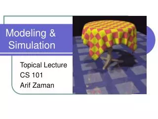
Toy Illustrations of Early Sub Geometry Concepts Captured as Major Surface Geometry
NSRP Panel Project Assess how the expanded and persistent use of simpler surface model representations for Naval vessels (both surface ships and submarines) will facilitate the creation of full-ship analysis models.
AP218: Ship Structures AP218 semantics have a decided surface ship flavor. Does AP218 apply equally well for submarine structures? Tank Structure Structural System
AP218 Implicit Geometry is Advantageous Parts and Features have Parametric Definitions Outward Round Corner Cutout Bulbflat Cross Section Drain Hole Cutout T Bar Cross Section
AP218 Files are Verbose Will they scale for full-ship scenarios?
NSRP Panel Project – Details • Approach and Scope: • More efficient methods for creation of analysis and simulation models are needed. • Analysis and simulation has a role across all design phases (or possibly all lifecycle stages); the earlier the better for concurrent engineering. • Both CAE-Centric and CAD-Centric approaches are necessary for analysis model creation, depending on the scale, scope and purpose of the simulation or analysis, as well as the design phase. • More persistent use of attributed surface geometry has advantages for creating shell analysis models. • AP218 may have particular benefit – need to examine and define.
Approach and Scope (Cont’d.): • The NSRP ASE/ISE paradigm (use of both or either P21 and/or P28) is accepted (at least by this group). • Well-ordered sequences of events exist and apply in shipbuilding design evolution from concept formulation to preliminary design to detailed design. • The shipbuilding ISO STEP Application Protocols for data exchange mirror this orderly progression (at least as it pertains to ship structure) AP215-AP216-AP218. • AP218 would appear to have adequate ship structure information necessary for the creation of structural ship shell analysis models.
Approach and Scope (Cont’d.): • Can or does AP218 apply equally well for submarine structural models? • Are there any things missing (gaps) in AP218 for use with submarines? If so, we will define and describe them. • Do the AP216 and AP218 data models scale appropriately to a full ship? Are there issues - verboseness, duplicity, etc.? • Is AP218 too focused on manufacturing? (Four or five of the nine current Conformance Classes for exchange are so defined.) • The implicit (parametric) geometry definitions in AP218 are desirable. If anything, they do not go far enough.
Approach and Scope (Cont’d.): • Explicit geometry definitions are generally adequate for CAD-CAE data exchange, being snapshots at points in time or in design stages. • Explicit geometry can be created on-the-fly when needed; e.g. solids-on-demand of the older NNS wsVIVID tool, Intergraph's ISDP & IntelliShip codes, or that briefly demonstrated at the ISE-4 Final Demonstration (4/06). • Is the AP218 data model complete enough to form the basis of a persistent CAD-CAE ship structural geometry repository? • Or should AP218 be relegated to its current status as a simple data exchange mechanism?
Benefits • Reduced cost, faster development of models for simulations of ships and Naval vessels • New approaches may present advantages over traditional forms of finite element model generation employing CAD systems & FEA tools • Reduced M&S cost by employing simpler attributed surface models (throughout the various design process stages) • Leverages recent interoperability initiatives (ISE)
NSRP Panel Project Goal Assess how the expanded use of simpler surface model representations for Naval vessels (both surface ships and submarines) will facilitate the creation of full-ship analysis models. Scope Develop and publish an integrated plan to create a more-automated capability or system for rapid generation of FEA full-ship models. Work is underway in other areas to automate ship mesh generation. The purpose of this plan would be to integrate these activities and allow and accommodate the use of the ship APs, and to unify the approach for both surface ships and submarines.
We Need More Balance in Analysis Model Creation (e.g. FEA) Geometry is not always the same! CAD-Centric CAE-Centric Idealized Simulation Geometry Analysis Model (FEM) Nominal CAD Geometry A mechanical engineer, a structural engineer, and a piping engineer may each require different forms of geometry capture. Both CAD-Centric and CAE-Centric processes are needed.
We Need More Balance in Analysis Model Creation (e.g. FEA) A Traditional CAD-Centric Process CAD-Centric Change Type or “Gender” Idealized Simulation Geometry Analysis Model (FEM) Nominal CAD Geometry Simplify Idealize De-Feature Pave Mesh Discretize Too Inefficient at Full Ship Scales
We Need More Balance in Analysis Model Creation (e.g. FEA) A CAE-Centric Process CAE-Centric Idealized Simulation Geometry Analysis Model (FEM) Nominal CAD Geometry Pave Mesh Discretize Add Req’d. Features More Efficient Creation of Shell Analysis Models
During Later Detailed Design Stages the Ship Product Model has a Manufacturing FlavorThe modern submarine has ~225,000 Structural Parts (of the 1.2 Million Overall Parts)There are Over 5000 Parts in the Hull “Weight Account” AloneAt this scale, Extracting All Appropriate Structural Data and Information for Creating Simulation Models can be Onerous and very Time-Consuming