Download
1 / 58
640 likes | 868 Views
Logic Circuit Design. Teacher 1 : Wei-Ru Lai ( 賴薇如 ) wrlai@saturn.yzu.edu.tw Room: 70812 Telphone: 7330 Teacher 2 : Yawgeng Chau( 趙耀庚老師 ) eeyaw@saturn.yzu.edu.tw. Text Book and Reference. Textbook M. Morris Mano and Michael D. Ciletti, Digital Design, 4th edition, Pearson Education.

E N D
Logic Circuit Design Teacher 1:Wei-Ru Lai (賴薇如) wrlai@saturn.yzu.edu.tw Room: 70812 Telphone: 7330 Teacher 2:Yawgeng Chau(趙耀庚老師) eeyaw@saturn.yzu.edu.tw
Text Book and Reference • Textbook • M. Morris Mano and Michael D. Ciletti, Digital Design, 4th edition, Pearson Education. • Reference book • Charles H. Roth, Jr., Fundamentals of Logic Design, 5th edition, West Publishing Co., 1992. • A First Course in Digital System Design, An Integrated Approach, John P. Uyemura, Georgia Institute of Technology. Books/Cole Publishing Company
Course Time • A班 • Friday 7,8,9 (14:10 - 17:00) • B班 • Tuesday 7,8,9 (14:10 - 17:00) • Classroom: 70205 • Office Hour: Wednesday 13:10-14:30 70812R
TeacherAssistant (1/2) • 黃郁文 • Office: 70831 • Telephone: 7011 – 831 • s974828@mail.yzu.edu.tw • 廖文豪 • Office: 70826 • Telephone: 7011 – 826 • s974802@mail.yzu.edu.tw
Teacher Assistant (2/2) • 陳之彥 • Office: 70938 • Telephone: 7011 – 938 • s974830@mail.yzu.edu.tw
Web Site • IP address: 140.138.178.54 or pcs.eed.yzu.edu.tw • Handout, old examination questions • Portal • Information, ex: Time and place of quiz • Handout, solution of homework • Discussion • It’s necessary to watch these web sites.
Course Structure • Lectures with power points • Discussions • Chapter-Based Homework • Announced in the Web Portal • Solution will be given later. • Exams • 邏輯電路實驗 (A:郭李瑞老師,B:高翊展老師)
Evaluation • 賴薇如老師 50% • Class Show-Up (4%) • Tests (8%*3=24%) • Mid exam (22%) • 趙耀庚老師 50% • Class Show-up (4%) • Text (8%*2=16%) • Final exam (30%)
Requirements for Class • Take your textbook in class. • Take notes in class. • Ask questions if you don’t understand. • Do your homework by yourself. • Don’t chat in class. Esteem your teachers, TAs and classmates.
Change Your Mindset (1/2) • Adapt yourself to the new environments, new teachers, and new teaching methods. • If you have any suggestion, tell me as soon as possible. • Read the textbook written in English. • You should spend a lot of times in this course.
Change Your Mindset (2/2) • 用功不是不缺席與寫作業而已,還包括要預習、 複習、 不懂時要肯發問、 寫錯答案要更正,要學會有效率的學習。 • Find your favorite department. • Try to achieve the basic requirements of our departments.
必修主科段考均應嚴格監考 • 包括助教在內,要有兩人以上監考。 • 隨機排定考試座位表。 • 考生桌面只有紙筆等應考物品,手機書包等一律放教室四周。 • 發完考卷後,強調將嚴格監考,發現考試作弊者將一律依校規退學,並宣讀『誠實考試宣言』如下: 我 (考生簽名) ,秉持誠實考試之原則,在此宣告本次XXX 考試,絕對遵守考試規則不作弊,否則願受最嚴厲之校規處置(退學)! • 在『考試座位表』及『誠實考試宣言』簽名。
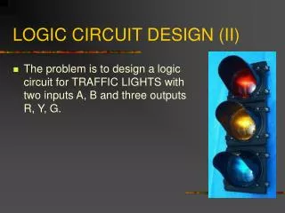
What is About This Course? Logic Circuit Design
邏輯電路設計在課程中的定位 大一上 大一下 大二上 大二下 大三上 大三下 大四上 大四下 數位系統設計與實驗 線性 代數 程式 設計 計算機概論 邏輯電路設計 微電腦系統 VHDL 設計 嵌入式系統原理及實驗 微電腦實驗 邏輯電路實驗 電子學 資料 結構
Logic Circuit Design • Digital electronic circuits are the engines of cell phones, MPEG players, digital cameras, computers, data servers, personal digital devices, GPS displays, and many other consumer products that process and use informationin a digital format. • Logic Circuit Design is an introductory course for the above industries.
Digital Computer data program
Wireless Phone • RF : Radio Frequency • AD : Analog-to-Digital • DA : Digital-to-Analog • BB : Baseband • DSP : Digital Signal Processing • RAM : Random Access Memory • ROM : Read Only Memory
0 0 0 1 1 0 1 1 1 1 0 0 1 1 1 0 1 1 1 0... 0 1 2 3 3 0 3 2 3 2 0... Analog (類比) vs. Digital (數位) • Analog system • The physical quantities or signals may vary continuously over a specified range. • Digital system • The physical quantities or signals can assume only discrete values.
Analog Signals (1/2) • All nature signals are analog. • Human voice, electromagnetic wave of handset, photograph, voice sent from handset, watercolor • It is intuitive to handle analog signals for storage, computation, and communication etc.
Analog Signals (2/2) • Nature signals are all analog. • Distortion(失真): the wave is distorted due to attenuation or noise. • If an analog signal is distorted, it is difficult to regenerate a original one. source distorted data
Analog or Digital? • The differences between analog systems and digital systems are the idea to view and process the data. • Analog view: every amplitude is meaningful in every moment. Everyqualify between 0-5V is meaningful. • Digital view: only 0 & 1
volt 5 4 logic 1 3 2 Unknown 1 logic 0 0 1 0 1 0 Digital Signals • Define a nature signal as 0 or 1. • We can interpret, store, send/receive or perform some operations on 0 and 1.
Digitalize(數位化) • Binary system, only 0 &1! • Try to transferthe nature signal to a series of 0s and 1s. • Discrete elements of information are represented with groups of bits are called binary codes (i.e., a pattern of 0’s and 1’s). • Ex: 510=01012 • Ex: A=0100 0001 (41H) • Therefore, binary system is enough.
Audio System Analog data Digital data
Sampling (取樣) • To achieve some discrete values from the originally continuous signalsis called as sampling. • These discrete values are called discrete signal(離散信號)or samples(取樣點). • Sampling rate(取樣頻率)is the times to achieve discrete signals per second. • Ex: If we get 8000samples per second, the sampling rate is 8000Hz.
Quantization (量化) • If the length of 0/1 bit stream is finite, the number of amplitude quantities that can be represented by these bit streams(referred to quantization level量化準位)is finite. • To find a relative level for each sample is called quantization(量化). • The distance between the sample and its quantization level is called quantization error(量化誤差).
Coding (編碼) • Coding(編碼): use a series of 0s and 1s to represent every quantization level. • Pulse Code Modulation(PCM)used in PSTN is 8-bit coding and 256quantization level. • The sampling rate is 8KHz. 64,000 bits are sent per second. That is, the data rate is 64,000bps.
Sampling Theorem (取樣定理) • Sampling Theorem(取樣定理)or Nyquist Theorem: Sampling rate must be twice (or more) of the original data rates. • For example, the frequency of human voiceis about 300-3400Hz. Then the sampling rate in PSTN is 8000Hz.
01010011 even parity 0 1 0 1 Advantages of Digital Signals • It is easy to distinguish between 0 and 1 even though the digital signal is distorted. • Distorted digital signal can be regenerated. • Special encoding schemes is used for error detection or error correction • Encryption can prevent from eavesdropping.
Accuracy • Operation in analogsystems: the error (i.e., distortion) will be accumulated. • Ex: to compute 6 mV *100=600 mV. • These is an error 0.1 mV. • Finally, 5.9mV *100=590 mV • Operation in digitalsystems: the error will not be accumulated. • Ex: 1102*11001002=1001011002 • Digital systems are capable of greater accuracy.
More and More Digital Systems • Programmable digital devices • Dramatic cost reductions • Reliability of data storage or communication by using error-correcting codes • The interconnection of smaller digital modules forms a larger system.
Digital System • A digital system is an electronic network that manipulates discrete elements of information represented internally in binary form. • Ex: answer machine, video game, CD • The work of digital systems • Transfer analog signals to digital signals. • Perform operations by 0 and 1. • Transfer the results to analogsignals.
Questions • How to store 0 and 1 by physical devices? • How to perform the operations of 0 and 1 by these physical devices? • Ex: How to do “1+1=10”? • What is the basic physical devices? • What is the basic digital operation? • Answer: AND, OR, NOT, NOR, NAND and XOR logic gates.
Switching Devices (1/2) • Two-state devices: the output can assume only two different discrete values. • Example of switching devices: relays, diodes, transistors. volt On Drain 5 Gate 4 logic 1 Transistor 3 Source 2 Unknown 1 logic 0 0 Off
Switching Devices (2/2) • Connecting several switching devicesmay perform operations of 0 and 1. That is, you have created a binary system. • We can use binary system to represent the circuits made by switching devices. A B F 0 0 +V 0 +V +V +V 0 +V +V +V 0 NAND Gate
Circuit Design • Circuit design involves specifying the interconnection of specific components such as resistors, diodes, and transistors to form logic gates, flip-flops, or other basic logic building blocks. • To design Integrated circuit (IC) • Electronics, VLSI (Very Large Scale Integrated circuits), Practicum of VLSI
Logic Design • Logic design involves determining how tointerconnectbasic logic building blocks to performa specific function. • Basic block: logic gates, latches, flip-flops • Larger blocks: additions, registers, counters, multiplexers, CPLD, FPGA A B F 0 0 1 0 1 1 1 0 0 1 1 1
HA Half Adder (HA) x Sum y Carry • x + y = Sum with a Carry • Sum = A XOR B • Carry = A AND B x y Carry Sum 0 0 0 0 0 1 0 1 1 0 0 1 1 1 1 0 Half Adder um arry
FA Full Adder (FA) x Sum y Carry z
S-R Latch • To store 0 or 1. • Use OR/NOT gates to construct a larger component! S P L S P R Q A new block Q R
Storage • Four-bit register
Binary Counter • Four-bit synchronous binary counter 0000→0001→0010→0011→0100→0101→0110→ … →1101 →1110→1111
Theory in the Logic Design • “Logic Design” tells us the theory necessary for understanding the logic design process. • Boolean algebra: the binary number system used in the logic design. • Implement technologies of digital systems are improved fast. However, its background theory is never changed.
Combinational Circuits • The output values depend only on the present value of the inputs and not on past values.
Sequential Circuits • The outputs depend on the present value of the inputs and past input values. • Basic memory elements: flip-flops feedback
Switching Circuits • Both combinational circuits and sequential circuits are called as switching circuits. • Computer Science, Practicum of Digital Circuit