1 / 0

Chapter 11 Disc Scheduling

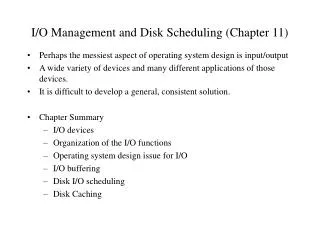
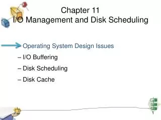
Chapter 11 Disc Scheduling. CS 345. Chapter 11 Learning Objectives. After studying this chapter, you should be able to: Summarize key categories of I/O devices on computers. Discuss the organization of the I/O function. Explain some of the key issues in the design of OS support for I/O.

ruana
Download Presentation

Chapter 11 Disc Scheduling

An Image/Link below is provided (as is) to download presentation Download Policy: Content on the Website is provided to you AS IS for your information and personal use and may not be sold / licensed / shared on other websites without getting consent from its author. Content is provided to you AS IS for your information and personal use only. Download presentation by click this link. While downloading, if for some reason you are not able to download a presentation, the publisher may have deleted the file from their server. During download, if you can't get a presentation, the file might be deleted by the publisher.

E N D

Presentation Transcript


  1. Chapter 11Disc Scheduling

  2. CS 345 Disc Scheduling
  3. Chapter 11 Learning Objectives After studying this chapter, you should be able to: Summarize key categories of I/O devices on computers. Discuss the organization of the I/O function. Explain some of the key issues in the design of OS support for I/O. Analyze the performance implications of various I/O buffering alternatives. Understand the performance issues involved in magnetic disk access. Explain the concept of RAID and describe the various levels. Understand the performance implications of disk cache. Describe the I/O mechanisms in UNIX, Linux, and Windows 7. Disc Scheduling
  4. Disk Structure Addressed as a one dimensional array of logical sectors Logical mapping to physical sectors on disk Sectors are smallest addressable blocks (usually 512 bytes) Clusters composed of one or more sectors Simple, but…….. Defective sectors Hidden by substituting sectors from elsewhere Number of sectors per track is not constant 40% more sectors on outside track Disc Scheduling
  5. Disk Structure Disc Scheduling
  6. Disk speed Disc Scheduling
  7. Disk Performance Much slower than memory Typical disk speed: 4-10 ms (10-3 s) Typical memory speed: 1-10 ns (10-9 s) I/O bus Protocols EIDE – Enhanced Integrated Drive Electronics ATA – Advanced Technology Attachment SATA – Serial ATA USB – Universal Serial Bus FC – Fiber Channel SCSI – Small Computer System Interface SAS – Serial SCSI IDE – Integrated Disk Electronics Disc Scheduling
  8. Effective Transfer Rates Performance measures Seek Time – Time to move the heads Approximation  (# of tracks × c) + startup/settle time Rotational Delay – Waiting for the correct sector to move under the head Average 1/2 rotation HD: 5400rpm ® 5.6ms, 10000rpm ® 3ms Floppy: 300 rpm ® 100ms Effective Times Access Time – Sum of seek time and rotational delay Transfer Time – Actual time needed to perform the read or write Time depends on locality Disc Scheduling
  9. Disk scheduling When a read/write job is requested, the disk may currently be busy All pending jobs are placed in a disk queue could be scheduled to improve the utilization Disk scheduling increases the disk’s bandwidth (the amount of information that can be transferred in a set amount of time) Disc Scheduling
  10. Disk Scheduling Random Select a random request to do next Worst possible performance, but useful for comparisons FIFO Do in the order they arrive Simple and fair in that all requests are honored Poor performance if requests are not clustered Especially true in multiprogramming systems Priority Do operations for high-priority processes first Not intended to optimize disk utilization, but to meet other objectives Users may try to exploit priorities Disc Scheduling
  11. Disk Scheduling LIFO (Last-In First-Out) Always take the most recent request Hope to catch a sequence of reads at one time (locality) Runs risk of starvation SSTF (Shortest Service Time First) Select the read closest to the current track next Requires knowledge of arm position Also has risk of starvation SCAN Arm moves in one direction, meeting all requests en route If no more requests, switch directions Bias against track just traversed Will miss locality in the wrong direction Favors innermost and outermost tracks; latest arriving jobs Disc Scheduling
  12. Disk Scheduling C-SCAN (circular SCAN) Always scan in one direction If no more requests, move to far end and start over Reduces time for requests on edges N-step Scan Prevent one track from monopolizing disk (“arm stickiness”) Have sub-queues of size N Use SCAN for each sub-queue FSCAN When one scan begins, only existing requests are handled New requests are put on a secondary queue When a scan ends, take the queue entries and start a new scan Disc Scheduling
  13. FCFS Scheduling Cylinder Requests: 53, 98, 183, 37, 122, 14, 124, 65, 67 0 14 37 53 65 67 98 122 124 183 199 Disc Scheduling
  14. SSTF Scheduling (Shortest seek time first) Cylinder Requests: 53, 98, 183, 37, 122, 14, 124, 65, 67 0 14 37 53 65 67 98 122 124 183 199 A form of Shortest Job First Not optimal May cause starvation Disc Scheduling
  15. SCAN Scheduling (Scan one side to other) Cylinder Requests: 53, 98, 183, 37, 122, 14, 124, 65, 67 0 14 37 53 65 67 98 122 124 183 199 Sometimes called the elevator algorithm Think about requests when head reverses direction - Just serviced those requests near disk head Disc Scheduling
  16. C-SCAN Scheduling (Circular Scan) Cylinder Requests: 53, 98, 183, 37, 122, 14, 124, 65, 67 0 14 37 53 65 67 98 122 124 183 199 Designed to provide more uniform wait time Treat cylinders like a circular list Disc Scheduling
  17. LOOK and C-LOOK Cylinder Requests: 53, 98, 183, 37, 122, 14, 124, 65, 67 0 14 37 53 65 67 98 122 124 183 199 Don’t go all the way to the end cylinders C-LOOK Disc Scheduling
  18. Disk Scheduling Algorithms Disc Scheduling
  19. Choosing an Algorithm Seek time is the only thing that can be controlled SSTF is commonly used (appealing) SCAN & CSCAN perform better under heavy load Why? (Think about starvation issues) Can find optimal schedule but computation is expensive In low use systems, FCFS is fine Disc Scheduling
  20. Choosing an Algorithm Head movement isn’t the only consideration Rotational Latency File system will play a part as well Typically file systems generate requests to read or write a larger unit of data (say 64K) and this request will be passed to the disk as a command to read or write 128 sectors. Hardware can help too Caching a whole track at a time The disk device initially transfers data to a memory chip in the disk controller circuitry. The cheapest desktop computer disks have 2 megabytes of cache memory, while for a few dollars more you can get a disk with 8 megabytes. Disc Scheduling
  21. Low-level Formatting When made, a disk is just a magnetic plate Low-level (or physical) formatting divides the disks into sectors MFM, M2FM Missing CLocks Header data – 512 bytes trailer Sector number Disk controller info ECC Disc Scheduling
  22. Disk formatting Logical formatting file system structure is written onto the disk Includes boot information (when requested) and FAT tables or inodes Boot sector contains enough instructions to start loading the OS from somewhere else Called by bootstrap program in computer’s ROM Disc Scheduling
  23. Bad blocks In FAT, when a block gives an unrecoverable ECC error, the sector is marked bad (0xFF7) in the FAT Bit mapped allocation just marks sector as used Some systems keep a pool of spare blocks when a block goes bad, maps the logical sector to one of the spare blocks Same cylinder if possible Sector slipping (push down a group to free up a sector) Doesn’t recover the corrupted file, but does keep the same logical disk structure Disc Scheduling
  24. Asynchronous I/O Application makes request and proceeds Ways to signal completion Signal a device kernel object Simple to handle Cannot distinguish multiple requests regarding the same file Signal a event kernel object Can create a separate object for each request Alertable I/O I/O manager places results in APC (asynchronous procedure call) queue I/O completion ports Use a pool of threads to handle requests RAID Hardware – Done by disk controller Software – System combines space Disc Scheduling
  25. Swap Space Swap Space This is the area of the disk where processes or memory pages are written if the system needs more physical memory Can be either set aside area of disk or part of the regular file system Set aside an area of the disk for swap space: Easier management and better performance Requires special code Part of file system: Uses regular file functions Slower to access and change Disc Scheduling
  26. Reliability Although disks are fairly reliable - they still fail on a regular basis Redundant arrays of independent disks (RAID) are more reliable Simplest forms have duplicate copies of each disk Twice the cost but twice as fast when reading Another type uses 1 parity block per 8 disk blocks The parity can be used to recalculate the information in a bad block Disc Scheduling
  27. RAID Database designers recognize that a H/W component can only be pushed so far… If the data is on separate disks, we can issue parallel commands This can be individual requests or a single large request Provide physical redundancy Industry has a standard for multiple-disk database design: RAID - Redundant Array of Independent Disks Key advantage: Combines multiple low-cost devices using older technology into an array that offers greater capacity, reliability, speed, or a combination of these things, than is affordably available in a single device using the newest technology. Disc Scheduling
  28. RAID Common characteristics Views a set of physical disks as a single logical entity Data is distributed across the disks in the array Use redundant disk capacity to be able to respond to disk failure Addresses the need for redundancy Caveat: More disks ® more chance of failure Disc Scheduling
  29. Raid Product Examples… IBM ESS Model 750 Disc Scheduling
  30. strip 0 strip 1 strip 2 strip 3 strip 4 strip 5 strip 6 strip 7 strip 9 strip 10 strip 11 strip 8 strip 13 strip 15 strip 14 strip 12 Array Management Software Data Mapping for RAID 0 Array Physical Disk 0 Physical Disk 1 Physical Disk 2 Physical Disk 3 strip 0 strip 1 strip 2 strip 3 strip 4 strip 5 strip 6 strip 7 strip 8 strip 9 strip 10 strip11 strip 12 strip 13 strip 14 strip 15 Disc Scheduling
  31. RAID RAID 0 Use of multiple disks means that a single request can be handled in parallel Greatly reduces I/O transfer time Also may balance load across disks Does not use redundancy RAID 1 Mirror data: read from either disk; writes update both disks in parallel Failure recovery easy Principle disadvantage is cost Disc Scheduling
  32. Hamming Codes Forward Error Correction (FEC) refers to the ability of receiving station to correct a transmission error. The transmitting station must append information to the data in the form of error correction bits, but the increase in frame length may be modest relative to the cost of re-transmission. Hamming codes provide for FEC using a "block parity" mechanism that can be inexpensively implemented (XOR). Hamming codes are used as an error detection mechanism to catch both single and double bit errors or to correct single bit error. This is accomplished by using more than one parity bit, each computed on different combination of bits in the data. Disc Scheduling
  33. RAID (continued…) RAID 2 Parallel access – All disks participate in each I/O request Uses Hamming codes to correct single-bit errors, detect double-bit errors Spindles synchronized Strips small (byte or word) Overkill – not used RAID 3 Implements a single parity strip with a single redundant disk Parity = data1  data2  data3  ... Missing data can be reconstructed from the parity strip and remaining data strips Capable of high data rates, but only one I/O request at a time Failure operates in reduced mode Disc Scheduling
  34. RAID (continued…) RAID 4-6 Independent access techniques RAID 4 Parity strip handled on a block basis Parity strip must be updated on each write Parity disk tends to be a bottleneck RAID 5 Like RAID 4, but distributes parity strips across all disks Disc Scheduling
  35. RAID (continued…) RAID 6 Use two different data check methods Can handle a double-disk failure Extremely high data availability w/substantial write penalty Disc Scheduling
  36. Striping 0 Non-redundant Large strings: Excellent Small strips: Excellent Applications requiring high performance for non-critical data Mirroring 1 Mirrored Good/fair Fair/fair System drives; critical files Parallel access 2 Redundant via Hamming code Poor Excellent 3 Bit-interleaved parity Poor Excellent Large I/O request size applications such as imaging, CAD Independent access 4 Block-interleaved parity Excellent/fair Fair/poor 5 Block-interleaved distributed parity Excellent/fair Fair/poor Applications requiring extremely high availability 6 Block-interleaved dual distributed parity Excellent/poor Fair/poor RAID Level Summary Category Description I/O Request Rate (Read/Write) Data Transfer Rate (Read/Write) Typical Application Disc Scheduling
  37. Disk Cache Similar concept to memory cache Use main memory to hold frequently used disk blocks to exploit the principle of locality Can afford more complex algorithms due to the time factors involved Handling a request If the data is in cache, pass it to the user (copy or use shared memory) If not in cache, read from the disk and add to the cache Replacement algorithms LRU – Can keep a list and determine the one not used for most time Most commonly used algorithm LFU (least frequently used) Account for how often it is used Watch out for burst of uses, then idle Improved performance w/frequency-abased Disc Scheduling
More Related