Download
1 / 55
560 likes | 568 Views
RF Plasma Sources and How to Use Helicons. Francis F. Chen Professor Emeritus, UCLA. Semes Co., Ltd., Chungnam, Korea, February 15, 2012. SHEATH. Plasma is necessary for etching. UCLA. Three kinds of RF discharges. Capacitively Coupled Plasmas (CCPs),

E N D
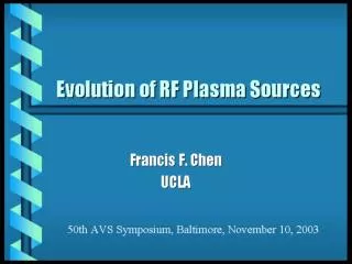
RF Plasma Sources and How to Use Helicons Francis F. Chen Professor Emeritus, UCLA Semes Co., Ltd., Chungnam, Korea, February 15, 2012
SHEATH Plasma is necessary for etching UCLA
Three kinds of RF discharges • Capacitively Coupled Plasmas (CCPs), • formerly called Reactive Ion Etchers (RIEs) • Inductively Coupled Plasmas (ICPs) • Helicon Wave Sources (HWS) UCLA
Sheaths keep a plasma neutral UCLA UCLA
Sheaths are very thin numerically, Let Then Debye sheaths are approximately 5lD thick UCLA UCLA
The Child-Langmuir Law The Debye (normal) sheath has a voltage drop of about 5KTe. If additional voltage is applied, a CL sheath forms with only ions. ions only quasi-neutral ions and electrons d V 3/4 + + + + UCLA UCLA
UCLA Most of the volume is sheath • Electrons are emitted by secondary emission ( and modes) • Ionization mean free path is shorter than sheath thickness () • Ionization occurs in sheath, and electrons are accelerated • into the plasma (gamma mode) • Why there is less oxide damage is not yet known
Effect of frequency on plasma density profiles 13.56 MHz 27 MHz 40 MHz 60 MHz
UCLA Problems with the original CCP discharges • The electrodes have to be inside the vacuum • Changing the power changes both the density and • the sheath drop • Particulates tend to form and be trapped • Densities are low relative to the power used • In general, too few knobs to turn to control the ion • and electron distributions and the plasma uniformity
UCLA Ion velocity distribution can be adjusted by applying low frequencies to substrate High frequency controls plasma density Low frequency controls ion motions and sheath drop Thin gap. Unequal areas to increase sheath drop on wafer
UCLA CCPs are great for large gas feed Fast and uniform gas feed for depositing amorphous silicon on very large glass substrates for displays (Applied Komatsu)
Inductively Coupled Plasmas (ICPs) The antenna can be on top or on the side TCP (Transformer Coupled Plasma) PlasmaTherm etcher
Or it can be a combination Applied Materials patent UCLA
RF B-field pattern comparison Lam type AMAT type UCLA
Early AMAT system UCLA
How can the RF energy get inside? The Plasma-Therm etcher UCLA
UCLA Explanation 1: electron path with Lorentz force
UCLA Electrons spend more time near center
Explanation 2: Sheaths at endplates The Simon short-circuit effect at endplates causes an electric field to develop that drives the ions inwards, and the electrons can “follow” even across magnetic fields. UCLA
Disadvantages of stove-top antennas • Skin depth limits RF field penetration. Density falls • rapidly away from antenna • If wafer is close to antenna, its coil structure is seen • Large coils have transmission line effects • Capacitive coupling at high-voltage ends of antenna • Less than optimal use of RF energy UCLA
H = J B = m H UCLA Coupling can be improved with a magnetic cover UCLA
The ferrite is inside the vacuum Meziani, Colpo, and Rossi, Plasma Sources Science and Technology 10, 276 (2001) UCLA
Fluxtrol F improves both RF field and uniformity (Meziani et al.)
SungKyunKwan Univ. Korea Magnets are used in Korea(G.Y. Yeom)
SungKyunKwan Univ. Korea Both RF field and density are increased
Magnets Serpentine antennas (suggested by Lieberman)
Density uniformity in two directions G.Y. Yeom, SKK Univ., Korea
Effect of wire spacing on density (calc.) Park, Cho, Lee, Lee, and Yeom, IEEE Trans. Plasma Sci. 31, 628 (2003)
In helicon sources, an antenna launches waves in a dc magnetic field The RF field of these helical waves ionizes the gas. The ionization efficiency is much higher than in ICPs.
Why are helicon discharges such efficient ionizers? The helicon wave couples to an edge cyclotron mode, which is rapidly absorbed.
A commercial helicon etcher (PMT MØRI) It required two heavy electromagnets with opposite currents.
Replace heavy electromagnet with small permanent magnet and Design of an array source with small tubes UCLA
Antenna must be short so that a short tube can be used An m = 0 loop antenna can generate plasma near the exit aperture. Note the “skirt” that minimizes eddy currents in the flange. A long antenna requires a long tube, and plasma goes to wall before it gets out. UCLA
The low-field peak: constructive interference The tube length is designed to maximize rf energy absorption R is the plasma resistance, which determines the RF power absorbed by the plasma,
Use the far-field of the magnet NdFeB material, 3”x 5”x1” thick Bmax = 12 kG
An 8-tube staggered array in operation UCLA UCLA
The magnet tray The magnets are dangerous! UCLA