Download
1 / 58
580 likes | 595 Views
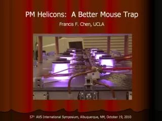
How helicons started: 1962. 3kW 17 MHz 500G. UCLA. How helicons started: 1970 - 85. 1 kW, 1 kG, argon n = 1013 cm-3 10X higher than normal. UCLA. In helicon sources, an antenna launches waves in a dc magnetic field. The RF field of these helical waves ionizes the gas.

E N D
How helicons started: 1962 3kW 17 MHz 500G UCLA
How helicons started: 1970 - 85 1 kW, 1 kG, argon n = 1013 cm-3 10X higher than normal
UCLA In helicon sources, an antenna launches waves in a dc magnetic field The RF field of these helical waves ionizes the gas. The ionization efficiency is much higher than in ICPs.
A large number of problems arose • Absorption mechanism and efficiency • Weakm = –1 mode and the Big Blue Mode • Downstream density peak, axial ion flow • Non-monotonic axial decay • Triangular radial profile • Mass-dependent density limit • Low-field density peak (~30G) • Density jumps with increasing B0, Prf • Half-wave antenna better than full-wave • Endplate charging with small diameters • High ion temperatures • Parametric instabilities UCLA
The Landau damping hypothesis In Landau damping, electrons surf on the wave The helicon’s phase velocity is close to that of an electron near the peak of the ionization cross section (~100eV) UCLA
Landau damping disproved A fast (RF) energy analyzer was built and calibrated RF modulated electron gun for calibration 2-electrode gridded analyzer with RF response D.D. Blackwell and F.F. Chen, Time-resolved measurements of the EEDF in a helicon plasma,Plasma Sources Sci. Technol. 10, 226 (2001) UCLA
Time-resolved EEDFs show no fast electronsabove a threshold of 10 -4 I-V swept by oscillating Vs I-V at two RF phases Loading resistance agrees with calculations w/o L.D. Injecting a current causes a beam-plasma instability
The Trivelpiece-Gould mode absorption mechanism • Helicon waves are whistler waves confined to a cylinder. • Their frequencies are << c, so that normally me 0 is OK. • However, if me 0, the dispersion relation has another root. • The new root is an electron cyclotron wave in a cylinder. It is called a Trivelpiece-Gould (TG) mode. • The TG mode exists in a thin layer near the surface and is damped rapidly in space, since it is slow. The helicon wave has weak damping. • This mechanism was suggested by Shamrai and Taranov of Kiev, Ukraine, in 1995. UCLA
Why are helicon discharges such efficient ionizers? The helicon wave couples to an edge cyclotron mode, which is rapidly absorbed.
The H and TG waves differ in k k|| This axis is essentially k UCLA
Detection of TG mode was difficult An RF current probe had to be developed UCLA
A large number of problems arose • Absorption mechanism and efficiency • Weakm = –1 mode and the Big Blue Mode • Downstream density peak, axial ion flow • Non-monotonic axial decay • Triangular radial profile • Mass-dependent density limit • Low-field density peak (~30G) • Density jumps with increasing B0, Prf • Half-wave antenna better than full-wave • Effect of endplates and endplate charging • High ion temperatures • Parametric instabilities UCLA
Types of antennas RH and LH helical Nagoya Type III Boswell double saddle coil 3-turn m = 0 UCLA
The m = +1 (RH) mode gives much higher density RH mode LH mode UCLA
m = +1 mode much stronger than m = –1 D.D. Blackwell and F.F. Chen, 2D imaging of a helicon discharge,Plasma Sources Sci. Technol.6, 569 (1997) m = –1 m = +1
UCLA Reason m = -1 mode is not easily excited m = +1 m = -1 The m = -1 mode has a narrower wave pattern; hence, it couples weakly to the TG mode at the boundary.
The Big Blue Mode The dense core (n = 1013-14 cm-3) is due to neutral depletion, allowing Te to increase No Faraday shield With shield
A large number of problems arose • Absorption mechanism and efficiency • Weakm = –1 mode and the Big Blue Mode • Downstream density peak, axial ion flow • Non-monotonic axial decay • Triangular radial profile • Mass-dependent density limit • Low-field density peak (~30G) • Density jumps with increasing B0, Prf • Half-wave antenna better than full-wave • Endplate charging with small diameters • High ion temperatures • Parametric instabilities UCLA
Machine used for basic studies r ~ 5 cm L ~ 160 cm B 1kG, Prf 2kW @ 13-27 MHz, 1-10 MTorr Ar UCLA
Symmetric and asymmetric antennas The maximum density occurs DOWNSTREAM, while Te decays. This is due to pressure balance: nKTe = constant. UCLA
Non-monotonic decay of wave downstream Oscillations are due to beating of radial modes with different k||. Theory fails as density changes further out. Average decay rate agrees with collisional damping. UCLA
Triangular density profiles Nonlinear diffusion, coupled with a bimodal ionization source, can explain "triangular" density profiles. UCLA
A large number of problems arose • Absorption mechanism and efficiency • Weakm = –1 mode and the Big Blue Mode • Downstream density peak, axial ion flow • Non-monotonic axial decay • Triangular radial profile • Mass-dependent density limit • Low-field density peak (~30G) • Density jumps with increasing B0, Prf • Endplate charging with small diameters • Half-wave antenna better than full-wave • High ion temperatures • Parametric instabilities UCLA
Mass-dependent density limit As B0 is increased, n rises but saturates at a value depending on the ion mass. This effect was first observed by T. Shoji. UCLA
A drift-type instability occurs M. Light (Ph.D. thesis) found that an instability occurs at a critical field and causes the density to saturate. This is the oscillation spectrum for neon. He identified the instability as a drift-Kelvin Helmholtz instability and worked out the theory for it. M. Light, F.F. Chen, and P.L. Colestock, Plasma Phys. 8, 4675 (2001), Plasma Sources Sci. Technol. 11, 273 (2003) UCLA
Anomalous diffusion results Outward particle flux was measured with n – f correlations, agreeing with that calculated quasilinearly from the growth rate. UCLA
Density limit due to neutral depletion Axial density profile with two 2-kW antennas 1m apart UCLA
A large number of problems arose • Absorption mechanism and efficiency • Weakm = –1 mode and the Big Blue Mode • Downstream density peak, axial ion flow • Non-monotonic axial decay • Triangular radial profile • Mass-dependent density limit • Low-field density peak (~30G) • Density jumps with increasing B0, Prf • Endplate charging with small diameters • Half-wave antenna better than full-wave • High ion temperatures • Parametric instabilities UCLA
A density peak occurs at low B-fields The cause is the constructive interference of the reflected wave from a bidirectional antenna UCLA
HELIC computations of plasma resistance Vary the B-field Vary the endplate distance Uni- and b-directional antennas Vary the with endplate conductivity
The end coils can also be turned off or reversed to form a cusped B-field The field lines then end on the glass tube, which forms an insulting endplate. An aperture limiter can also be added.
A cusp field or and end block can greatly increase the density G. Chevalier and F.F. Chen, Experimental modeling of inductive discharges, J. Vac. Sci. Technol. A11, 1165 (1993)
A large number of problems arose • Absorption mechanism and efficiency • Weakm = –1 mode and the Big Blue Mode • Downstream density peak, axial ion flow • Non-monotonic axial decay • Triangular radial profile • Mass-dependent density limit • Low-field density peak (~30G) • Density jumps with increasing B0, Prf • Endplate charging with small diameters • Half-wave antenna better than full-wave • High ion temperatures • Parametric instabilities UCLA
Discharge jumps into helicon modes n vs. B-field n vs. RF power R.W. Boswell, Plasma Phys. Control. Fusion 26, 1147 (1984) UCLA
W: helicon H: inductive E: capacitive Transition to helicon mode A.W. Degeling and R.W. Boswell, Phys. Plasmas 4, 2748 (1997) UCLA
UCLA A new interpretation of the jumps The power into the plasma depends on the plasma loading (Rp) and the circuit losses (Rc) If Rp is too small, the input power is less than the losses. The jump into helicon mode can be computed from theoretical Rp’s. The critical power agrees with experiment. F.F. Chen and H. Torreblanca, Plasma Sources Sci. Technol. 16, 593 (2007)
A large number of problems arose • Absorption mechanism and efficiency • Weakm = –1 mode and the Big Blue Mode • Downstream density peak, axial ion flow • Non-monotonic axial decay • Triangular radial profile • Mass-dependent density limit • Low-field density peak (~30G) • Density jumps with increasing B0, Prf • Endplate charging with small diameters • Half-wave antenna better than full-wave • High ion temperatures • Parametric instabilities UCLA
A large number of problems arose • Absorption mechanism and efficiency • Weakm = –1 mode and the Big Blue Mode • Downstream density peak, axial ion flow • Non-monotonic axial decay • Triangular radial profile • Mass-dependent density limit • Low-field density peak (~30G) • Density jumps with increasing B0, Prf • Endplate charging with small diameters • Half-wave antenna better than full-wave • High ion temperatures • Parametric instabilities UCLA
Half wavelength helical antennas are betterthan full wavelength antennas L. Porte, S.M. Yun, F.F. Chen, and D. Arnush, Superiority of half-wavelength helicon antennas,LTP-110 (Oct. 2001)
A large number of problems arose • Absorption mechanism and efficiency • Weakm = –1 mode and the Big Blue Mode • Downstream density peak, axial ion flow • Non-monotonic axial decay • Triangular radial profile • Mass-dependent density limit • Low-field density peak (~30G) • Density jumps with increasing B0, Prf • Endplate charging with small diameters • Half-wave antenna better than full-wave • High ion temperatures • Parametric instabilities UCLA
Anomalously high ion temperatures Unusually high Ti’s are observed by laser induced fluorescence. This happens near lower hybrid resonance, but no special heating is expected there. J.L. Kline, E.E. Scime, R.F. Boivin, A.M. Keesee, and X. Sun, Phys. Rev. Lett. 88, 195002 (2002).
A large number of problems arose • Absorption mechanism and efficiency • Weakm = –1 mode and the Big Blue Mode • Downstream density peak, axial ion flow • Non-monotonic axial decay • Triangular radial profile • Mass-dependent density limit • Low-field density peak (~30G) • Density jumps with increasing B0, Prf • Endplate charging with small diameters • Half-wave antenna better than full-wave • High ion temperatures • Parametric instabilities UCLA
The energy absorption mechanism near the antenna may be nonlinear, involving parametric decay of the TG wave into ion acoustic waves Lorenz, Krämer, Selenin, and Aliev* used: 1. Test waves in a pre-formed plasma 2. An electrostatic probe array for ion oscillations 3. Capacitive probes for potential oscillations 4. Microwave backscatter on fluctuations 5. Correlation techniques to bring data out of noise *B. Lorenz, M. Krämer, V.L. Selenin, and Yu.M. Aliev, Plasma Sources Sci.Technol. 14, 623 (2005).
A helicon wave at one instant of time Note that the scales are very different! UCLA
Damping rate in the helicon afterglow The damping rate increases with Prf, showing the existence of a nonlinear damping mechanism. UCLA