Download
1 / 36
360 likes | 479 Views
Hydraulic Servo and Related Systems ME4803 Motion Control. Wayne J. Book HUSCO/Ramirez Chair in Fluid Power and Motion Control G.W. Woodruff School of Mechanical Engineering Georgia Institute of Technology. Hydraulics is Especially critical to the Mobile Equipment Industry. References.

E N D
Hydraulic Servo and Related SystemsME4803 Motion Control Wayne J. Book HUSCO/Ramirez Chair in Fluid Power and Motion Control G.W. Woodruff School of Mechanical Engineering Georgia Institute of Technology
Hydraulics is Especially critical to the Mobile Equipment Industry
References • Norvelle, F.D. Fluid Power Control Systems, Prentice Hall, 2000. • Fitch, E.C. and Hong I.T. Hydraulic Component Design and Selection, BarDyne, Stillwater, OK, 2001. • Cundiff, J.S. Fluid Power Circuits and Controls, CRC Press, Boca Raton, FL, 2002. • Merritt, H.E. Hydraulic Control Systems, John Wiley and Sons, New York, 1967. • Fluid Power Design Engineers Handbook, Parker Hannifin Company (various editions). • Cetinkunt, Sabri, Mechatronics, John Wiley & Sons, Hoboken, NJ, 2007.
The Strengths of Fluid Power(Hydraulic, to a lesser extent pneumatic) • High force at moderate speed • High power density at point of action • Fluid removes waste heat • Prime mover is removed from point of action • Conditioned power can be routed in flexible a fashion • Potentially “Stiff” position control • Controllable either electrically or manually • Resulting high bandwidth motion control at high forces • NO SUBSTITUTE FOR MANY HEAVY APPLICATIONS
Difficulties with Fluid Power • Possible leakage • Noise generated by pumps and transmitted by lines • Energy loss due to fluid flows • Expensive in some applications • Susceptibility of working fluid to contamination • Lack of understanding of recently graduated practicing engineers • Multidisciplinary • Cost of laboratories • Displaced in curriculum by more recent technologies
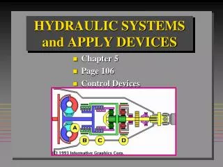
Volts-amp System Overview Electric or IC prime mover Transmission line & valve Flow-press. Motor or cylinder Rpm-torque or force Rpm-torque Flow-press. Pump • The system consists of a series of transformation of power variables • Power is either converted to another useful form or waste heat • Impedance is modified (unit force/unit flow) • Power is controlled • Function is achieved Coupling mechanism Rpm-torque or force Load
Simple open-loop open-center circuit cylinder Actuating solenoid Spring return Pressure relief valve 4-way, 3 position valve filter Fixed displacement pump Fluid tank or reservoir
Closed-loop (hydrostatic) system Motor Check valve Variable displacement reversible pump Drain or auxiliary line
Basic Operation of the Servo Valve(single stage) Flow exits Flow enters Torque motor moves spool right Torque motor moves spool left Positive motor rotation Negative motor rotation
p0 ps p0 x p2, q2 p1, q1 4 Way Proportional Spool Valve Model • Spool assumptions • No leakage, equal actuator areas • Sharp edged, steady flow • Opening area proportional to x • Symmetrical • Return pressure is zero • Zero overlap • Fluid assumptions • Incompressible • Mass density
p0 ps p0 x p2, q2 p1, q1 Dynamic Equations (cont.)
q1 Change in volume y Net area Ap Change in density Dynamic Equations: the Actuator • If truly incompressible: • Specification of flow without a response in pressure brings a causality problem • For example, if the piston has mass, and flow can change instantaneously, infinite force is required for infinite acceleration • Need to account for change of density and compliance of walls of cylinder and tubes
Compressibility of Fluids and Elasticity of Walls For the pure definition, the volume is fixed. More useful here is an effective bulk modulus that includes expansion of the walls and compression of entrapped gasses Using this to solve for the change in pressure
m q dy/dt 1/A q Area A feedback load pressure may reduce q q p dv/dt dy/dt k dt dt A/m A Choices for modeling the hydraulic actuator(simplified actuator) Change of variables: consider q as volumetric flow rate With no compliance or compressibility we get actuator velocity v as y With compliance and/or compressibility combined into a factor k And with moving mass m we get the following block diagram. Steady state (dy/dt)/q is the same. Transient is different. (Show with final value theorem.) -
Two-stage Servo Valve With flapper centered the flow and pressure is balanced Torque motor rotates flapper, obstructs left nozzle Feedback spring balances torque motor force Pressure increases Spool is driven right Flow gives negative rotation
Details of Force Feedback Design 2 Sharp edged orifices, symmetrical opening Shown line to line; no overlap or underlap
Position Servo Block Diagram Flow gain / motor displacement Position measurement Load torque Net flow / displacement Proportional control May be negligible
Design of some components(with issues pertinent to this class) • Flow • Darcy’s formula • Orifice flow models • Stress • Thin-walled tubes (t<0.1D) • Thick-walled tubes (t>0.1D) • Guidelines • Fluid speed • Strengths • Factors of safety (light service: 2.5, general: 3.15, heavy: 4-5 or more) • The conduit (tubing) is subject to requirements for • flow (pressure drop) • 2 to 4 ft/sec for suction line bulk fluid velocity • 7 to 20 ft/sec for pressure line bulk fluid velocity • pressure (stress) • The piston-cylinder is the most common actuator • Must withstand pressure • Must not buckle
Buckling in the Piston Rod (Fitch) • Rod is constrained by cylinder at two points • Constrained by load at one point • Diameter must resist buckling • Theory of composite “swaged column” applies • Composite column fully extended is A-B-E shown below consisting of 2 segments • A-B segment buckles as if loaded by force F on a column A-B-C • B-E segment buckles as if loaded by F on DBE • Require tangency at B
Results of Composite Column Model Equating the slope of the two column segments at B where they join yields: Composite column model matches manufacturer’s recommendations with factor of safety of 4
Cylinder construction (tie-rod design) Resulting loading on cylinder walls
Pressure Specifications • Nominal pressure = expected operating • Design pressure = Nominal • Proof pressure (for test) = 2x Design • Burst pressure (expect failure) = 4x Design
Pipes versus tubes • Tubes are preferred over pipes since fewer joints mean • Lower resistance • Less leakage • Easier construction
Fittings between tube and other components require multiple seals Flared tube design