Download
1 / 30
310 likes | 513 Views
HYDRAULIC SYSTEMS and APPLY DEVICES. Chapter 5 Page 106 Control Devices. CONTROL DEVICES. The oil pump is the source of all fluid flow through the Trans. The valve body regulates and directs fluid flow to provide gear changes. Page 106. VALVE TYPES. CHECK VALVES Ball valves

E N D
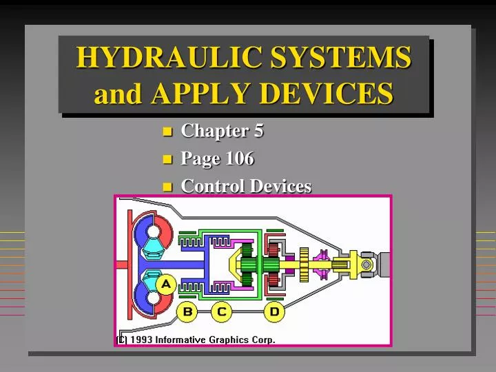
HYDRAULIC SYSTEMS and APPLY DEVICES • Chapter 5 • Page 106 • Control Devices
CONTROL DEVICES • The oil pump is the source of all fluid flow through the Trans. • The valve body regulates and directs fluid flow to provide gear changes. Page 106
VALVE TYPES CHECK VALVES • Ball valves • Poppet valves • Needle valves • REGULATION VALVES • Relief valves • Orifices • Spool valves Page 106
CHECK VALVES • One way valve • To stop back flow • Directional control valve • Figure 5-14 page 107
RELIEF VALVES • A check valve fitted with a spring will not open until hydraulic pressure becomes greater than spring force. • Figure 5-16 Page 108
ORIFICES • Orifices are used in transmissions to control dynamic pressures. • A number of orifices are often placed in series to provide a cushioning effect on the hydraulic system. • Orifices are used for gradual activation of an apply device, which improves shift quality. Page 108
SPOOL VALVES • Spool valves are the most commonly used valve in a transmission. • Spools are precisely machined to fit into a bore and are connected by the valves stem. • The stem has a smaller diameter than the spools. • The stem is not a precisely machined part of the valve. Page 109
CONTROL VALVES • A flow directing fluid to different outlet ports. Page 110
RELAY VALVES • A relay valve is a spool valve with several spools, lands, and reaction areas. • It is used to control direction of flow. • Does not control pressure. Page 110
VALVE BODIES Page 110
PRESSURES • All automatics use 3 basic pressures to control their operation: • Mainline Pressure - Pressure Regulator valve • Throttle Pressure - Throttle valve • Governor Pressure - Governor Valve Page 110
BOOST PRESSURES • Line pressure is a regulated pump pressure. • Increasing pressure increases holding power of bands & clutches. • Throttle pressure is applied to a booster valve at the PR. • Some transmissions use two boost valves. Page 113
PRESSURE REGULATOR VALVE • Pressure will increase with engine speed. • PR valves use the principles of both pressure relief and a spool valve. • Some PR valves use 3 types of boost - TV, Manual 1, Reverse. Page 113
Pressure Regulator Valve • Action of vane-type pump: • Maximum output • page 106
Pressure Regulator Valve • Action of vane-type pump: • Minimum output • page 106
GOVERNORS • Spool valve type • Check ball type Page 115
VEHICLE SPEED SENSOR • There are three types of speed sensors. • Magnetic pulse generator - most common • Hall effect switch • Optical sensor Page 117
LOAD SENSOR • Shift timing and quality should vary with engine load, as well as vehicle speed. • There are three ways to do this: • Vacuum modulator • TV cable or linkage • Map sensor and computer Page 117
VACUUM MODULATOR • Uses engine vacuum to sense engine load and adjust line pressure and shift points. Page 117
THROTTLE LINKAGES • Uses a cable or linkage to sense engine load and adjust line pressure and shift points. Page 118
THROTTLE LINKAGES • Adjust throttle linkage before TV linkage Page 118
MAP SENSOR • Manifold Absolute Pressure Sensor • MAP sensor generates a voltage in direct relation to engine load. • 0 to 5 volts Page 120
SHIFT TIMING • Shift timing is determined by throttle position and governor pressure acting on opposite ends of the shift valve. • When accelerating at a steady rate governor pressure will overcome a steady throttle pressure and cause the shift valve to stroke up-shifting the transmission. Page 120
SHIFT VALVES • Shift valves are spool valves. • Movement of the shift valve is controlled by: • A spring holding the valve in the down-shift position. • Changing throttle pressure holding the shift valve in the down-shift position. • Governor pressure increasing with road speed forcing the shift valve to the upshift position.. Page 120
MANUAL VALVE • The manual valve is a spool valve manually operated by the gear selector linkage. Page 120
KICKDOWN VALVE • Vacuum, electrical, or linkage signals are sent to the valve body causing a sudden increase in throttle pressure. • Actual downshift is controlled in many ways. Page 120
ELECTRONIC SHIFT-TIMING CONTROLS • Sensor inputs • Actuator outputs Page 121
SOLENOID VALVES • Most solenoid-operated valves are ball-type valves that open and close a hydraulic passage. Page 121
OIL CIRCUITS • Trace one circuit at a time. • Start at the oil pump. Page 121