Download
1 / 101
1.01k likes | 1.01k Views
Learn the stages and purposes of creating UML class diagrams, including exploratory domain models and system models. Discover techniques for identifying classes, associations, attributes, generalizations, and responsibilities. Apply design patterns and ensure a balanced and organized diagram.

E N D
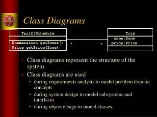
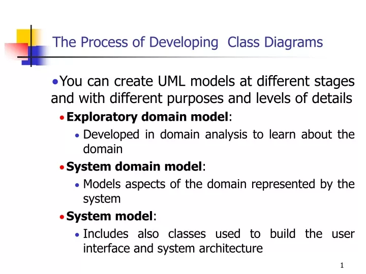
The Process of Developing Class Diagrams • You can create UML models at different stages and with different purposes and levels of details • Exploratory domain model: • Developed in domain analysis to learn about the domain • System domain model: • Models aspects of the domain represented by the system • System model: • Includes also classes used to build the user interface and system architecture
System domain model vs System model • The system domain model omits many classes that are needed to build a complete system • Can contain less than half the classes of the system. • Should be developed to be used independently of particular sets of • user interface classes • architectural classes • The complete system model includes • The system domain model • User interface classes • Architectural classes • Utility classes
Suggested sequence of activities • Identify a first set of candidate classes • Add associations and attributes • Find generalizations • List the main responsibilities of each class • Decide on specific operations • Iterate over the entire process until the model is satisfactory • Add or delete classes, associations, attributes, generalizations, responsibilities or operations • Identify interfaces • Apply design patterns (Chapter 6) • Don’t be too disorganized. Don’t be too rigid either.
Identifying classes • When developing a domain model you tend to discover classes • When you work on the user interface or the system architecture, you tend to invent classes • Needed to solve a particular design problem • (Inventing may also occur when creating a domain model) • Reuse should always be a concern • Frameworks • System extensions • Similar systems
A simple technique for discovering domain classes • Look at a source material such as a description of requirements • Extract the nouns and noun phrases • Eliminate nouns that: • are redundant • represent instances • are vague or highly general • not needed in the application • Pay attention to classes in a domain model that represent types of users or other actors
Identifying associations and attributes • Start with classes you think are most central and important • Decide on the clear and obvious data it must contain and its relationships to other classes. • Work outwards towards the classes that are less important. • Avoid adding many associations and attributes to a class • A system is simpler if it manipulates less information
Tips about identifying and specifying valid associations • An association should exist if a class • possesses • controls • is connected to • is related to • is a part of • has as parts • is a member of, or • has as members some other class in your model • Specify the multiplicity at both ends • Label it clearly.
Actions versus associations • A common mistake is to represent actions as if they were associations Better: The operation creates a , and borrow Loan Bad, due to the use of associations the operation sets the return returnedDate that are actions attribute.
Identifying attributes • Look for information that must be maintained about each class • Several nouns rejected as classes, may now become attributes • An attribute should generally contain a simple value • E.g. string, number
Tips about identifying and specifying valid attributes • It is not good to have many duplicate attributes • If a subset of a class’s attributes form a coherent group, then create a distinct class containing these attributes
Identifying generalizations and interfaces • There are two ways to identify generalizations: • bottom-up • Group together similar classes creating a new superclass • top-down • Look for more general classes first, specialize them if needed • Create an interface, instead of a superclass if • The classes are very dissimilar except for having a few operations in common • One or more of the classes already have their own superclasses • Different implementations of the same class might be available
Allocating responsibilities to classes • A responsibility is something that the system is required to do. • Each functional requirement must be attributed to one of the classes • All the responsibilities of a given class should be clearly related. • If a class has too many responsibilities, consider splitting it into distinct classes • If a class has no responsibilities attached to it, then it is probably useless • When a responsibility cannot be attributed to any of the existing classes, then a new class should be created • To determine responsibilities • Perform use case analysis • Look for verbs and nouns describing actions in the system description
Categories of responsibilities • Setting and getting the values of attributes • Creating and initializing new instances • Loading to and saving from persistent storage • Destroying instances • Adding and deleting links of associations • Copying, converting, transforming, transmitting or outputting • Computing numerical results • Navigating and searching • Other specialized work
An example (responsibilities) • Creating a new regular flight • Searching for a flight • Modifying attributes of a flight • Creating a specific flight • Booking a passenger • Canceling a booking
Prototyping a class diagram on paper • As you identify classes, you write their names on small cards • As you identify attributes and responsibilities, you list them on the cards • If you cannot fit all the responsibilities on one card: • this suggests you should split the class into two related classes. • Move the cards around on a whiteboard to arrange them into a class diagram. • Draw lines among the cards to represent associations and generalizations.
Identifying operations • Operations are needed to realize the responsibilities of each class • There may be several operations per responsibility • The main operations that implement a responsibility are normally declared public • Other methods that collaborate to perform the responsibility must be as private as possible
Class collaboration ‘a’ 0..1 SpecificFlight Airplane * • Making a bi-directional link between two existing objects; • e.g. adding a link between an instance of SpecificFlight and an instance of Airplane. • 1. (public) The instance of SpecificFlight • makes a one-directional link to the instance of Airplane • then calls operation 2. • 2. (non-public) The instance of Airplane • makes a one-directional link back to the instance of SpecificFlight
Class collaboration ‘b’ 1 • Creating an object and linking it to an existing object • e.g. creating a FlightLog, and linking it to a SpecificFlight. • 1. (public) The instance of SpecificFlight • calls the constructor of FlightLog (operation 2) • then makes a one-directional link to the new instance of FlightLog. • 2. (non-public) Class FlightLog’s constructor • makes a one-directional link back to the instance of SpecificFlight.
Class collaboration ‘c’ 1 1 • Creating an association class, given two existing objects • e.g. creating an instance of Booking, which will link a SpecificFlight to a PassengerRole. • 1. (public) The instance of PassengerRole • calls the constructor of Booking (operation 2). • 2. (non-public) Class Booking’s constructor, among its other actions • makes a one-directional link back to the instance of PassengerRole • makes a one-directional link to the instance of SpecificFlight • calls operations 3 and 4. • 3. (non-public) The instance of SpecificFlight • makes a one-directional link to the instance of Booking. • 4. (non-public) The instance of PassengerRole • makes a one-directional link to the instance of Booking.
Class collaboration ‘d’ • Changing the destination of a link • e.g. changing the Airplane of to a SpecificFlight, from airplane1 to airplane2 • 1. (public) The instance of SpecificFlight • deletes the link to airplane1 • makes a one-directional link to airplane2 • calls operation 2 • then calls operation 3. • 2. (non-public) airplane1 • deletes its one-directional link to the instance of SpecificFlight. • 3. (non-public) airplane2 • makes a one-directional link to the instance of SpecificFlight.
Class collaboration ‘e’ • Searching for an associated instance • e.g. searching for a crew member associated with a SpecificFlight that has a certain name. • 1. (public) The instance of SpecificFlight • creates an Iterator over all the crewMember links of the SpecificFlight\ • for each of them call operation 2, until it finds a match. • 2. (may be public) The instance of EmployeeRole returns its name.
Implementing Class Diagrams in Java • Attributes are implemented as instance variables • Generalizations are implemented using extends • Interfaces are implemented using implements • Associations are normally implemented using instance variables • Divide each two-way association into two one-way associations • so each associated class has an instance variable. • For a one-way association where the multiplicity at the other end is ‘one’ or ‘optional’ • declare a variable of that class (a reference) • For a one-way association where the multiplicity at the other end is ‘many’: • use a collection class implementing List, such as Vector
Example: SpecificFlight class SpecificFlight { private Calendar date; private RegularFlight regularFlight; ... // Constructor that should only be called from // addSpecificFlight SpecificFlight( Calendar aDate, RegularFlight aRegularFlight) { date = aDate; regularFlight = aRegularFlight; } }
Example: RegularFlight class RegularFlight { private List specificFlights; ... // Method that has primary responsibility public void addSpecificFlight(Calendar aDate) { SpecificFlight newSpecificFlight; newSpecificFlight = new SpecificFlight(aDate, this); specificFlights.add(newSpecificFlight); } ... }
Interaction Diagrams • Interaction diagrams are used to model the dynamic aspects of a software system • They help you to visualize how the system runs. • An interaction diagram is often built from a use case and a class diagram. • The objective is to show how a set of objects accomplish the required interactions with an actor.
Interactions and messages • Interaction diagrams show how a set of actors and objects communicate with each other to perform: • The steps of a use case, or • The steps of some other piece of functionality. • The set of steps, taken together, is called an interaction. • Interaction diagrams can show several different types of communication. • E.g. method calls, messages send over the network • These are all referred to as messages.
Elements found in interaction diagrams • Instances of classes • Shown as boxes with the class and object identifier underlined • Actors • Use the stick-person symbol as in use case diagrams • Messages • Shown as arrows from actor to object, or from object to object
Creating interaction diagrams • You should develop a class diagram and a use case model before starting to create an interaction diagram. • There are two kinds of interaction diagrams: • Sequence diagrams • Collaboration diagrams
Sequence diagrams • A sequence diagram shows the sequence of messages exchanged by the set of objects performing a certain task • The objects are arranged horizontally across the diagram. • An actor that initiates the interaction is often shown on the left. • The vertical dimension represents time. • A vertical line, called a lifeline, is attached to each object or actor. • The lifeline becomes a broad box, called an activation box during the live activation period. • A message is represented as an arrow between activation boxes of the sender and receiver. • A message is labelled and can have an argument list and a return value.
Sequence diagrams – an example with replicated messages • An iteration over objects is indicated by an asterisk preceding the message name
Sequence diagrams – an example with object deletion • If an object’s life ends, this is shown with an X at the end of the lifeline
Communication diagrams • Communication diagrams emphasise how the objects collaborate in order to realize an interaction • A communication diagram is a graph with the objects as the vertices. • Communication links are added between objects • Messages are attached to these links. • Shown as arrows labelled with the message name • Time ordering is indicated by prefixing the message with some numbering scheme.
Communication links • A communication link can exist between two objects whenever it is possible for one object to send a message to the other one. • Several situations can make this message exchange possible: 1. The classes of the two objects have an association between them. • This is the most common case. • If all messages are sent in the same direction, then probably the association can be made unidirectional.
Other communication links 2. The receiving object is stored in a local variable of the sending method. • This often happens when the object is created in the sending method or when some computation returns an object. • The stereotype to be used is «local» or [L]. 3. A reference to the receiving object has been received as a parameter of the sending method. • The stereotype is «parameter» or [P].
Other communication links 4. The receiving object is global. • This is the case when a reference to an object can be obtained using a static method. • The stereotype «global», or a [G] symbol is used in this case. 5. The objects communicate over a network. • We suggest to write «network».
How to choose between using a sequence or communication diagram • Sequence diagrams • Make explicit the time ordering of the interaction. • Use cases make time ordering explicit too • So sequence diagrams are a natural choice when you build an interaction model from a use case. • Make it easy to add details to messages. • Communication diagrams have less space for this
How to choose between using a sequence or communication diagram • Communication diagrams • Can be seen as a projection of the class diagram • Might be preferred when you are deriving an interaction diagram from a class diagram. • Are also useful for validating class diagrams.
Communication diagrams and patterns • A communication diagram can be used to represent aspects of a design pattern
State Diagrams • A state diagram describes the behaviour of a system, some part of a system, or an individual object. • At any given point in time, the system or object is in a certain state. • Being in a state means that it is will behave in a specific way in response to any events that occur. • Some events will cause the system to change state. • In the new state, the system will behave in a different way to events. • A state diagram is a directed graph where the nodes are states and the arcs are transitions.
State diagrams – an example • tic-tac-toe game
States • At any given point in time, the system is in one state. • It will remain in this state until an event occurs that causes it to change state. • A state is represented by a rounded rectangle containing the name of the state. • Special states: • A black circle represents the start state • A circle with a ring around it represents an end state
Transitions • A transition represents a change of state in response to an event. • It is considered to occur instantaneously. • The label on each transition is the event that causes the change of state.
State diagrams – an example of transitions with time-outs and conditions