Download
1 / 14
140 likes | 341 Views
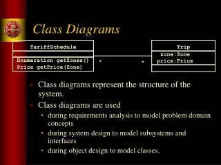
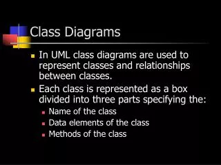
Class Diagrams. (Design) Class Diagrams (1). A class diagram is a visual representation of various classes and their relationships as identified during design. Information in class diagram includes: classes, associations, and attributes interfaces with operations and constants methods

E N D
Class Diagrams Class Diagrams
(Design) Class Diagrams (1) • A class diagram is a visual representation of various classes and their relationships as identified during design. • Information in class diagram includes: • classes, associations, and attributes • interfaces with operations and constants • methods • attribute type information • navigability • dependencies Class Diagrams
Class diagrams (2) • Class diagrams are generally created after or in parallel with the interaction diagrams. • Interaction diagrams are used to identify classes and the methods they provide. • Conceptual model is also useful in deriving classes by addition of detail. • Classes are considered software entities and not real-world concepts. Class Diagrams
Making class diagrams (1) • Identify all classes by examining interaction diagrams. • Draw them in a class diagram. • Duplicate the attributes from the associated concepts shown in the conceptual model. • Add method names by examining interaction diagrams. • Add type information to the attributes and methods. Class Diagrams
Making class diagrams (2) • Add the associations needed for visibility. • Add navigability arrows to indicate the direction of attribute visibility. • Add dependency relationships to indicate non-attribute visibility. Class Diagrams
Conceptual model versus class diagrams (1) • A Sale in a conceptual model represents a system concept. A Sale in a class diagram represents a software entity. Class Diagrams
captures 1 1 POST Sale Date isComplete: boolean time POST captures Sale 1 1 Date isComplete:boolean time Date isComplete:boolean time makeLineItem() Conceptual model versus class diagrams (2) Conceptual model Software components Class Diagrams
Class diagrams: notables (1) • create is a special language independent UML message to indicate instantiation and initialization. As this is a common operation, it is often omitted from class diagrams. • Access methods for class attributes are also omitted from class diagrams to reduce clutter. • Messages to a multiobject are not shown as methods in the class whose objects are contained in a multiobject. Class Diagrams
Class diagrams: notables (2) • It is recommended that UML syntax be used for method naming. This will keep naming language independent. UML format: methodName(parameterList) • Should all type information be shown in a class diagram? • If automatic code generation is desired then YES. • If the sole purpose is to use the diagram as a communication aid, then all type information is not of any significant value. (See Fig 21.7 of T1.) Class Diagrams
POST Sale Date isComplete:boolean time Date isComplete:boolean time makeLineItem() Class diagrams: navigability (1) Navigability arrow: POST objects are connected uni-directionally to Sale objects. POST will likely have an attribute pointing to Sale. captures 1 1 No navigability arrow..Sale does not have connection to POST. Class Diagrams
Class diagrams: navigability (2) • It is recommended that associations be adorned with navigability arrows. • Navigability is determined by visibility. • A sends a message to B. • A creates an instance of B. • A needs to maintain a connection to B. • Example: Examine Figures 21.9 and 21.10 on pages 266-267. Why are navigability arrows not provided in the conceptual model ? Class Diagrams
Class diagrams: dependency • In UML a dependency relationship indicates that one element has knowledge of another element. • It is illustrated with a dashed arrow. • Non-attribute visibility…arising from parameters, global, or locally declared items is illustrated by dashed arrows. • See Figure 21.11, page 268, for dependency relationships. Class Diagrams
Class diagrams: other notations • Initial values of attributes • Return value type • Abstract method • Parameters • Visibility Class Diagrams
Summary • What did we learn? • What is a class diagram ? • How to derive a class diagram from interaction diagrams ? • Notational details for class diagrams. Class Diagrams