Download
1 / 28
280 likes | 442 Views
Class Diagrams. Overview. Class diagrams are the most commonly used diagrams in UML. Class diagrams are for visualizing, specifying and documenting the system from a static perspective.

E N D
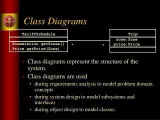
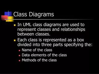
Overview • Class diagrams are the most commonly used diagrams in UML. • Class diagrams are for visualizing, specifying and documenting the system from a static perspective. • Class diagrams indicate which classes know about other classes and, if they do, what type of relationship exists. • Class diagrams will have different levels of detail (abstraction) depending on where we are in the software development process.
Overview • Class diagrams commonly contain classes, interfaces, collaborations and associations. • Class diagrams help in showing the functional requirements of the system - the services the system should provide to its end users.
Common Modeling Techniques • To model a collaboration (a group of classes working toward a common purpose) … • Use scenarios to see which classes are actually involved in carrying out a particular operation. • Scenarios will also aide in establishing relationships between classes. • Fill in the ‘responsibilities’ section of each class icon. • The responsibilities of each class will eventually evolve into actual attributes and behaviors. • A complex system typically requires multiple class diagrams. • Each diagram is devoted to a particular functionality of the system.
Common Modeling Techniques • To model a logical database schema … • Identify the persistent objects - objects that are stored on disk between runs of the program. • Label persistent objects as such in the class diagrams using tags or stereotypes.
Common Modeling Techniques • Multiple class diagrams are required to model large systems. • Each individual class diagram … • Shows a single aspect of the system. • Contains only elements that are essential to understanding that aspect. • Provide details consistent with its level of abstraction. • Uses meaningful class and member names. • Pointers to other classes are modeled as associations.
Overview • A classifier is a mechanism that describes structural and behavioral features. • Types of classifiers are … • classes, interfaces, datatypes, signals, components, nodes, use cases and subsystems. • Classes are the most important kind of classifier. • Classes have a number of features beyond attributes and behaviors that allow you to model some of the more subtle/advanced features of a system.
Terms and Concepts • Other classifier definitions: • Interface - A collection of operations that are used to specify a service of a class or component. • Datatype - Modeled as a class with the strerotype <<type>>. May be primitive or user-defined. • Signal - A class used for communicating information. The class in its entirety is a kind of message. • Component - A physical and replaceable part of a system that conforms to and provides the realization of a set of interfaces. • Node - A physical element that exists at run time and that represents a computational resource.
Terms and Concepts • Other classifier definitions: • Use case - A description of a set of a sequence of actions that yields an observable result of value to a particular actor. • Actor - An external user of the system. • Subsystem - A grouping of element that carry out a subset of the entire systems functionality. • Modeled as a package with the stereotype <<subsystem>>
Terms and Concepts • Visibility • Class members (attributes and behaviors) may be specified as public (+), private (-), or protected (#). • In UML the single character visibility indicator is placed to the left of the member. • # myProtectedFunction( ) • - myPrivateFunction( ) • + myPublicFunction( ) • Restricting visibility is the same as restricting accessibility. By restring accessibility you are limiting the number of entry points into an object. By restricting the number of entry points you are facilitating debugging and code re-use.
Terms and Concepts • Scope • Individual member data (attributes) may have either class scope or instance scope. • Class scope - A single copy of an attribute is shared by all instances of a class. • In UML you underline the attribute to indicate class scope: productCount : int • In C++ members with class scope would be declared as static: static int productCount • Instance scope - Each instance of a class would have its own copy of the attribute. All attributes have instance scope by default.
Terms and Concepts • Abstract • A abstract class cannot have any direct instances. • Not all OO programming languages directly support abstract classes. (In C++ abstract classes contain one or more pure virtual functions). • int myFunction(int x) = 0; • Pure virtual functions have no function body. • An abstract class is thought to be so general as to be useless by itself. • Abstract classes only occur in the context of an inheritance hierarchy. • In UML you specify that a class is abstract by writing its name in italics.
Terms and Concepts • Root and Leaf • Tags may be used to indicate that a class can have no parents ( {root} ) or children ( {leaf} ). There is rarely an occasion to use this feature.
Terms and Concepts • Polymorphism • Polymorphic behavior exists in the context of inheritance. • Polymorphism applies to behavior (member functions) only. • Polymorphism is synonymous with dynamic binding. • In UML a behavior name in italics is used to indicate polymorphism. • In C++ a polymorphic call would most likely appear as • (*baseClassPointer).poylmorphicFunction( ); • baseClassPointer -> poylmorphicFunction( );
Terms and Concepts • Multiplicity • Class multiplicity • In ULM it can be indicated by placing a number in the upper right corner of the class icon. • Most commonly expressed in the context of associations between classes. • Attribute multiplicity • In UML it is indicated as an expression appearing in square brackets just after the attribute name. • Looks like an array declaration in C++. • attributeName [4] : attributeType
Terms and Concepts • Attributes • May be expressed using various levels of detail. • The syntax for an attribute is • [visibility] name [multiplicity] [: type] [ = initialValue ] [{propertyTag}] • There are three predefined property tags • changeable - the attribute may be read and modified (default) • addOnly - when multiplicity > 1, additional objects may be added but not removed • frozen - read only (constant value) • The only feature of an attribute that is required in a class icon is its name.
Terms and Concepts • Operations (behaviors) • May be expressed using various levels of detail. • The syntax for an operation is • [visibility] name [(parameterList)] [: returnType] [{propertyTag}] • Predefined propertyTags are ... • isQuery - cannot change the state of the object. • Sequential - only one thread of control in the object at a time. • Guarded - pretty much the same as sequential • concurrent - multiple threads of control may be in the object simultaneously.
Terms and Concepts • Operations (behaviors) continued... • Each parameter has the syntax: • [direction] name : type [= defaultValue] • Directions may be in, out, or inout. • The only feature of an operation that is required in a class icon is its name.
Terms and Concepts • Templates are ... • A parameterized element. • Intended to facilitate software reusability. • Used to automate the creation of class definitions. • Similar to macros in assembly language. • Essentially a class definition with the data types of certain attributes yet to be defined. • Most commonly used to create container classes. • Represented in UML as a dashed box in the upper right-hand corner of the class icon, which lists the template parameters. • Directly supported in C++.
Common Modeling Techniques • A well-defined class is loosely coupled (few entry points) and highly cohesive (all members work toward a common functionality). • Ask yourself “Am I trying to show what the class does or how it does it”. That will tell you at what level of abstraction to model the class. • In the requirements and specification phase you are interested in “what”. In the design phase you are interested in “how”. • Don’t hesitate to attach notes to the class icons if further clarification is necessary.