Download

1 / 51
540 likes | 736 Views
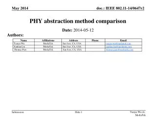
Three-Method Absolute Antenna Calibration Comparison. Andria Bilich (1) , Martin Schmitz (2) , Barbara Görres (3) , Philipp Zeimetz (3) , Gerald Mader (1) , Gerhard Wübbena (2). (1) NOAA / National Geodetic Survey. (2) Geo++ GmbH. (3) Institute for Geodesy and Geoinformation ,

E N D
Three-Method Absolute Antenna Calibration Comparison Andria Bilich(1), Martin Schmitz(2), Barbara Görres(3), Philipp Zeimetz(3), Gerald Mader(1), Gerhard Wübbena(2) (1) NOAA / National Geodetic Survey (2) Geo++ GmbH (3) Institute for Geodesy and Geoinformation, University of Bonn
Outline • Goals of Three-Method Comparison • Overview of Methods • Geo++ robot in field • Uni of Bonn robot in anechoic chamber • NGS robot in field • Comparison • Antennas tested • Results • Conclusions and Future Work
Goal of Study • NGS to demonstrate agreement with approved IGS calibration institutions • Send same antenna to 3 institutions • individual calibrations • For multiple absolute calibration methods/institutions to contribute to IGS ANTEX: • Establish compatibility (matching results) • Understand any differences • Evaluate different types of multi-frequency antennas • Geodetic (chokering or other multipath-rejecting reference station antenna) • Survey-grade (small, compact, often susceptible to near-field effects)
Geo++ GmbH • Contributing to IGS since 2006 • Operational since 2000 • Similar robots at Hannover and Berlin contribute to IGS • Robot in field • 3-axis, 5 degrees of freedom • Pivot point (~ L1/L2 PCO) remains fixed in space • All-in-view GNSS signals, JAVAD TRE_G3T receiver • Data analysis • Short baseline • Undifferenced phase data • Kalman filter
University of Bonn • Approved by IGS AWG in 2010 (no calibrations in igs08.atx yet) • Robot in anechoic chamber • 2-axis • Antenna boresight remains fixed in space • Simulated signal (sine wave at carrier frequency) • Network analyzer sends and receives
NOAA / NGS • Robot in field • Corbin, VA • 2-axis • PCO not fixed in space • All-in-view GPS signals • Data analysis • Short baseline • SeptentrioAsteRx receiver (both antennas) • Time-differences of single-differenced phase • Unfiltered For specifics, see poster “Absolute Antenna Calibration at the National Geodetic Survey”
Antennas in Comparison GPS L1/L2 only for this presentation.
Trimble Zephyr 2(TRM55971.00) One antenna sample tested
Trimble Zephyr 2 (TRM55971.00) Elevation-dependent PCV
Trimble Zephyr 2 (TRM55971.00) Convention for comparison: • Add together PCO and PCV into total antenna phase center • Reduce to antenna ARP • Maintain condition that total phase = 0 mm at zenith Elevation-dependent total phase
Trimble Zephyr 2 (TRM55971.00) L1 pattern size = 70 mm Differences in purely elevation-dependent PCV: • <= 1 mm • L1 above 10 • L2 except for bump at 20 and 45 • < 2 mm for L1 & L2 L2 pattern size = 65 mm
NGS – Bonn Trimble Zephyr 2 (TRM55971.00)GPS L1 differences Geo++ - Bonn NGS – Geo++
Trimble Zephyr 2 (TRM55971.00)GPS L1 differences NGS – Bonn Geo++ - Bonn NGS – Geo++
NGS – Bonn Trimble Zephyr 2 (TRM55971.00)GPS L2 differences Geo++ - Bonn NGS – Geo++
Trimble Zephyr 2 (TRM55971.00)GPS L2 differences NGS – Bonn Geo++ - Bonn NGS – Geo++
Trimble Zephyr 2Summary • Most of inter-method differences < 1 mm • Exceptions to the 1mm rule: • L1 below 10 elevation • L2 below 30 elevation • Majority of differences are < 2 mm (independent of azimuth and elevation)
Trimble GNSS Chokering(TRM59800.00) Three antenna samples tested
1 Trimble GNSS chokering(TRM59800.00) Serial # xxxx371
2 Trimble GNSS chokering(TRM59800.00) Serial # xxxx409
3 Trimble GNSS chokering(TRM59800.00) Serial # xxxx068
GPS L1 elevation-dependent differences 1 L1 pattern size = 130 mm 3 2
GPS L2 elevation-dependent differences 1 L2 pattern size = 100 mm 3 2
1 Trimble GNSS chokeringGPS L1 differences NGS – Bonn L1 pattern size = 130 mm Geo++ - Bonn NGS – Geo++
2 Trimble GNSS chokeringGPS L1 differences NGS – Bonn L1 pattern size = 130 mm Geo++ - Bonn NGS – Geo++
3 Trimble GNSS chokeringGPS L1 differences NGS – Bonn L1 pattern size = 130 mm Geo++ - Bonn NGS – Geo++
1 Trimble GNSS chokeringGPS L2 differences NGS – Bonn L2 pattern size = 100 mm Geo++ - Bonn NGS – Geo++
2 Trimble GNSS chokeringGPS L2 differences NGS – Bonn L2 pattern size = 100 mm Geo++ - Bonn NGS – Geo++
3 Trimble GNSS chokeringGPS L2 differences NGS – Bonn L2 pattern size = 100 mm Geo++ - Bonn NGS – Geo++
1 NGS – Bonn Trimble GNSS chokeringGPS L2 differences Geo++ - Bonn NGS – Geo++
2 NGS – Bonn Trimble GNSS chokeringGPS L2 differences Geo++ - Bonn NGS – Geo++
3 NGS – Bonn Trimble GNSS chokeringGPS L2 differences Geo++ - Bonn NGS – Geo++
In-depth Exploration of Chokering L2 Differences • Systematic differences • Is there a simple explanation? Geo++ - Bonn NGS – Geo++ NGS – Bonn
GPS L2 elevation-dependent differences … drift with respect to elevation angle is consistent with error in vertical PCO 1 3 2
Adjust Vertical PCO Add 3.5 mm to be consistent with other solutions Original PCO Estimated Modified Geo++ Vertical
GPS L2 elevation-dependent differences • Changing vertical PCO of one or more solution creates agreement: • Shown here: add 3.5 mm to Geo++ • Same effect from: • -4 NGS, -2 Bonn • -2 NGS, +2 Geo++ 1 3 2
1 Trimble GNSS chokeringGPS L2 differenceswith adjusted vertical PCO NGS – Bonn Geo++ - Bonn NGS – Geo++
1 NGS – Bonn Trimble GNSS chokeringGPS L2 differenceswith adjusted vertical PCO Geo++ - Bonn NGS – Geo++
Trimble GNSS ChokeringSummary • Good agreement for L1 (sub-mm) • Less ideal L2 agreement, differences are: • Systematic (same trends across samples) • Trends consistent with vertical PCO error • Area of active research for AWG • < 2mm above 30 elevation (not 10) • < 3-5 mm in the 0-20range
Conclusions • NGS has demonstrated agreement with Geo++ and Bonn for IGS-quality antennas ... • AWG active research to continue • Source of vertical PCO mis-estimation • Calibration effects on position • Near-field effects (robot, antenna mount) on calibration
Elevation-dependent PCV Topcon PG-A1 (TPSPG_A1+GP)
Topcon PG-A1 (TPSPG_A1+GP) Differences in purely elevation-dependent PCV: • L1 ± 2 mm • L2 ± 4 mm w/ bias • Extremely variable • Differences in L2 PCV are larger than PCV themselves
NGS Topcon PG-A1 (TPSPG_A1+GP)GPS L1 PCV Geo++ Bonn
NGS Topcon PG-A1 (TPSPG_A1+GP)GPS L2 PCV Geo++ Bonn
Topcon PG-A1 (TPSPG_A1+GP)GPS L1 PCV NGS Geo++ Bonn
Topcon PG-A1 (TPSPG_A1+GP)GPS L2 PCV NGS Geo++ Bonn
NGS – Bonn Topcon PG-A1 (TPSPG_A1+GP)GPS L1 differences Geo++ - Bonn NGS – Geo++
NGS – Bonn Topcon PG-A1 (TPSPG_A1+GP)GPS L2 differences Geo++ - Bonn NGS – Geo++
Topcon PG-A1 (TPSPG_A1+GP)GPS L1 differences NGS – Bonn Geo++ - Bonn NGS – Geo++