Download
1 / 1
20 likes | 184 Views
Ultrasonic Phased Array Imaging System. Kurt Matarese, Professor Michael Ruane. Department of Electrical and Computer Engineering, Boston University, Boston, MA, 02215.

E N D
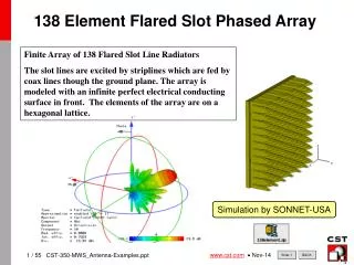
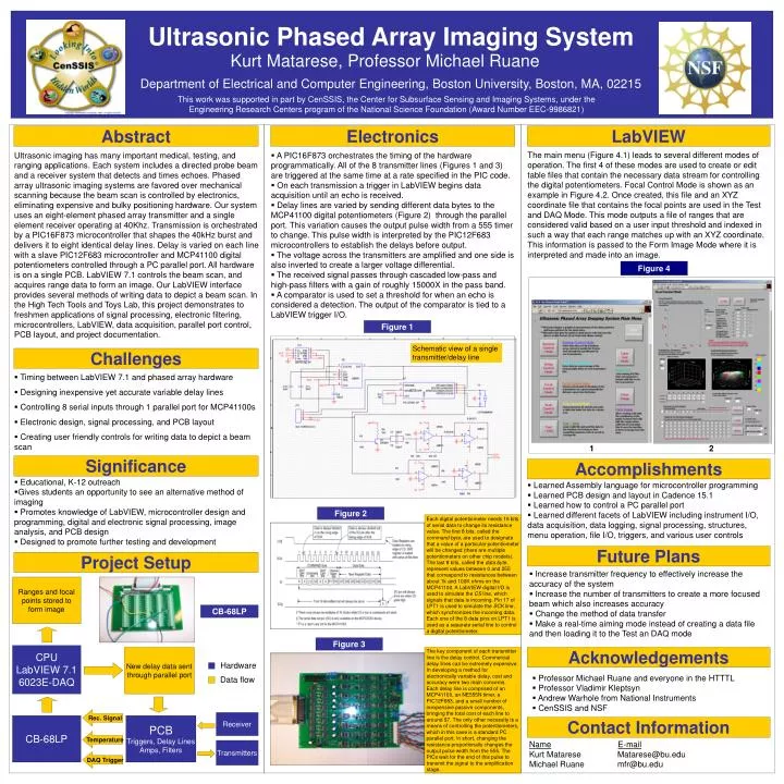
Ultrasonic Phased Array Imaging System Kurt Matarese, Professor Michael Ruane Department of Electrical and Computer Engineering, Boston University, Boston, MA, 02215 This work was supported in part by CenSSIS, the Center for Subsurface Sensing and Imaging Systems, under the Engineering Research Centers program of the National Science Foundation (Award Number EEC-9986821) Abstract Electronics LabVIEW The main menu (Figure 4.1) leads to several different modes of operation. The first 4 of these modes are used to create or edit table files that contain the necessary data stream for controlling the digital potentiometers. Focal Control Mode is shown as an example in Figure 4.2. Once created, this file and an XYZ coordinate file that contains the focal points are used in the Test and DAQ Mode. This mode outputs a file of ranges that are considered valid based on a user input threshold and indexed in such a way that each range matches up with an XYZ coordinate. This information is passed to the Form Image Mode where it is interpreted and made into an image. Ultrasonic imaging has many important medical, testing, and ranging applications. Each system includes a directed probe beam and a receiver system that detects and times echoes. Phased array ultrasonic imaging systems are favored over mechanical scanning because the beam scan is controlled by electronics, eliminating expensive and bulky positioning hardware. Our system uses an eight-element phased array transmitter and a single element receiver operating at 40Khz. Transmission is orchestrated by a PIC16F873 microcontroller that shapes the 40kHz burst and delivers it to eight identical delay lines. Delay is varied on each line with a slave PIC12F683 microcontroller and MCP41100 digital potentiometers controlled through a PC parallel port. All hardware is on a single PCB. LabVIEW 7.1 controls the beam scan, and acquires range data to form an image. Our LabVIEW interface provides several methods of writing data to depict a beam scan. In the High Tech Tools and Toys Lab, this project demonstrates to freshmen applications of signal processing, electronic filtering, microcontrollers, LabVIEW, data acquisition, parallel port control, PCB layout, and project documentation. • A PIC16F873 orchestrates the timing of the hardware programmatically. All of the 8 transmitter lines (Figures 1 and 3) are triggered at the same time at a rate specified in the PIC code. • On each transmission a trigger in LabVIEW begins data acquisition until an echo is received. • Delay lines are varied by sending different data bytes to the MCP41100 digital potentiometers (Figure 2) through the parallel port. This variation causes the output pulse width from a 555 timer to change. This pulse width is interpreted by the PIC12F683 microcontrollers to establish the delays before output. • The voltage across the transmitters are amplified and one side is also inverted to create a larger voltage differential. • The received signal passes through cascaded low-pass and high-pass filters with a gain of roughly 15000X in the pass band. • A comparator is used to set a threshold for when an echo is considered a detection. The output of the comparator is tied to a LabVIEW trigger I/O. Figure 4 Figure 1 Schematic view of a single transmitter/delay line Challenges • Timing between LabVIEW 7.1 and phased array hardware • Designing inexpensive yet accurate variable delay lines • Controlling 8 serial inputs through 1 parallel port for MCP41100s • Electronic design, signal processing, and PCB layout • Creating user friendly controls for writing data to depict a beam scan 1 2 Significance Accomplishments • Educational, K-12 outreach • Gives students an opportunity to see an alternative method of imaging • Promotes knowledge of LabVIEW, microcontroller design and programming, digital and electronic signal processing, image analysis, and PCB design • Designed to promote further testing and development • Learned Assembly language for microcontroller programming • Learned PCB design and layout in Cadence 15.1 • Learned how to control a PC parallel port • Learned different facets of LabVIEW including instrument I/O, data acquisition, data logging, signal processing, structures, menu operation, file I/O, triggers, and various user controls Figure 2 Each digital potentiometer needs 16 bits of serial data to change its resistance value. The first 8 bits, called the command byte, are used to designate that a value of a particular potentiometer will be changed (there are multiple potentiometers on other chip models). The last 8 bits, called the data byte, represent values between 0 and 255 that correspond to resistances between about 1k and 100K ohms on the MCP41100. A LabVIEW digital I/O is used to simulate the CS line, which signals that data is incoming. Pin 17 of LPT1 is used to simulate the SCK line, which synchronizes the incoming data. Each one of the 8 data pins on LPT1 is used as a separate serial line to control a digital potentiometer. Future Plans Project Setup • Increase transmitter frequency to effectively increase the accuracy of the system • Increase the number of transmitters to create a more focused beam which also increases accuracy • Change the method of data transfer • Make a real-time aiming mode instead of creating a data file and then loading it to the Test an DAQ mode Ranges and focal points stored to form image CB-68LP Figure 3 CPU LabVIEW 7.1 6023E-DAQ New delay data sent through parallel port The key component of each transmitter line is the delay control. Commercial delay lines can be extremely expensive. In developing a method for electronically variable delay, cost and accuracy were two main concerns. Each delay line is comprised of an MCP41100, an NE555N timer, a PIC12F683, and a small number of inexpensive passive components, bringing the total cost of each line to around $7. The only other necessity is a means of controlling the potentiometers, which in this case is a standard PC parallel port. In short, changing the resistance proportionally changes the output pulse width from the 555. The PICs wait for the end of this pulse to transmit the signal to the amplification stage. Acknowledgements Hardware • Professor Michael Ruane and everyone in the HTTTL • Professor Vladimir Kleptsyn • Andrew Warhole from National Instruments • CenSSIS and NSF Data flow Rec. Signal Receiver CB-68LP PCB Triggers, Delay Lines Amps, Filters Contact Information Temperature NameE-mail Kurt Matarese Matarese@bu.edu Michael Ruane mfr@bu.edu Transmitters DAQ Trigger