Download
1 / 18
220 likes | 436 Views
Electronics Soldering Basics. Presented by Richard Gowen (@ alt_bier ) Founding Board Member of TheLab.ms MakerSpace / HackerSpace in Plano This Slide Deck Is Available at http://solder.altbier.us/. Electronics Soldering.

E N D
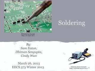
Electronics SolderingBasics Presented by Richard Gowen (@alt_bier)Founding Board Member of TheLab.msMakerSpace / HackerSpace in Plano This Slide Deck Is Available at http://solder.altbier.us/
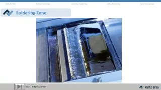
Electronics Soldering Soldering is a process in which two or more metal items are joined together by melting and then flowing a filler metal into the joint—the filler metal having a relatively low melting point. Electronics Soldering is used to form a permanent conductive connection between electronic components and printed circuit boards and/or wires. The metal to be soldered is heated with a soldering iron and then solder is melted into the connection. Due to its low melting point only the solder melts, not the parts being soldered. Solder is a metal that when melted between parts holds those parts together and forms a connection that allows electrical current to flow. You can use a solderless breadboard to make test circuits, but if you want a circuit to be permanent and exist without the breadboard, you will need to solder the components.
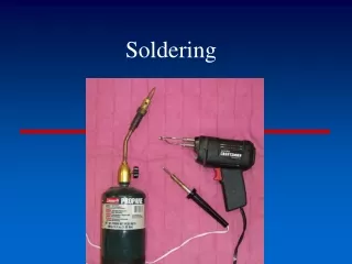
Soldering Equipment Soldering Iron Stand w/ Sponge Wire Tools There are many types of soldering irons for different applications. For best results with electronics you should look for one with a Wattage in the range of 20W to 60W depending upon the tip size (looking for tip temp of ~700 F) A soldering stand can be helpful in avoiding burns from the tip which takes time to cool even after being turned off. A damp sponge helps keep the tip of the iron free of solder buildup Wire tools such as strippers, cutters, and pliers help to prepare the components to be soldered.
Soldering Equipment immobilization Tools De-solder Tools Safety Equipment Any tools that can be used to hold the parts together while soldering them are considered immobilization tools. Examples include a Vise or Helping Hands Tools for de-soldering (removing solder from components) include solder suckers, solder pumps, and solder wick wires. Safety glasses should always be worn when soldering as applying heat to components always has the risk of something popping or splashing towards you. Optionally a safety mask could minimize the risk of fumes.
Soldering Materials Solder Flux There are many kinds of solder available in different thicknesses. Most solder is made of a 60/40 mix of tin(Sn) and lead(Pb). Some solder has a small amount of silver to provide for stronger joints. Lead free solder is available but has a higher melting point and is harder to work with. The use of lead is up to you but it is easier to work with for the beginner. For electronics it is usually best to use a smaller diameter solder wire such as 0.025”/0.64mm/22gauge. Flux is a material that improves contact and strength in solder joints and comes in two main types: Rosin and Organic AcidRosin is the flux used for electronics where Acid has other applications like plumbing. While Flux can be obtained separate from solder, many solder wires contain a core which is filled with flux to ensure consistent application. For electronics it is usually best to use solder wire with a Rosin Flux core.
Soldering Materials Electrical Components Printed Circuit Boards (PCB) There are many kinds of electrical components that can be soldered either to each other, to a wire, or to a PCB. These include Light Emitting Diodes (LED), resistors, capacitors, switches, relays, microcontrollers, and many more. Each component will have it’s own properties related to soldering. Such as heat resistance (how long to reach solder temp) heat tolerance (how much heat will destroy it) and connector types. You should carefully research the parts you intend to solder. There are many different kinds of printed circuits boards (PCB) that can be used for electronics applications. Some have one copper pad per hole requiring wires or bridge soldering to connect them. Some have groups holes that have pads that are interconnected. Some will be designed for use with specific components. You should choose the PCB type that best meets your projects needs.
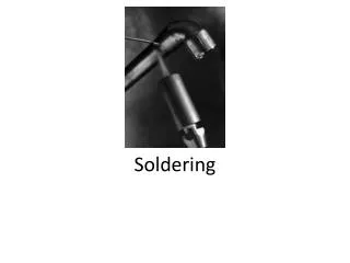
The Soldering Iron The soldering iron is a tool used to heat components which allows solder to be melted against them joining them together. The tip of a soldering iron should heat up to between 650o and 750o F depending upon the wattage of the iron (20-60W is typical for electronics) and the size and shape of the tip (a small chisel or pointed tip is typical). Various components have different heat resistance and thus there is no hard and fast rule about the exact temperature and amount of time to heat them. The iron should not be used to melt the solder directly. The goal is to heat the components to the point that solder melts against them. Care should be taken to avoid burns! When the iron is not in your hand it should be in a stand.
Preparing For Safety Always wear Safety Glasses or Goggles. Heating components and solder may cause these items to pop, spit, or splash towards you. RISK of projectile and/or burn injury. Never touch the element or tip of the soldering iron. It is extremely hot and take time to cool after being unplugged. Optionally you could wear Heat Resistant Gloves to prevent accidental burns. RISK of burn injury. Take care not to touch the tip of the iron to anything not intended to be soldered especially its own electrical cord. Clothing and other materials may catch fire. Melting the cord could cause a shock. RISK of electric shock and/or fire and/or burn injury. Always place the iron in a Safety Stand which fully encloses the hot areas when not in use. If its not in your hand it should be in a stand!RISK of fire and/or burn injury. Work in a well ventilated area and Never directly inhale the smoke/fumes coming from the tip of the iron. Lead and other toxins are released in these fumes.Optionally you could use a Safety Breathing Mask. RISK of illness. AlwaysWash Your Hands after soldering to remove lead and toxins. RISK of illness.
Preparing The Iron - Tinning Soldering irons get hot enough to melt metal, which means that their tips oxidize quickly just sitting in the air. These oxides (which make the tip look dirty) are an insulator for heat. So, we need to clean the tip and cover it in a thin coat of solder to delay oxidation and provide consistent heat flow. This procedure is called tinning. Here are the steps to proper tinning: • Scrape and roll a hot tip on a damp sponge to remove visible oxidants • Apply solder directly to the hot tip coating it evenly • Roll the hot solder covered tip on a damp sponge to remove excess solder. Tinning should be done before soldering is started and periodically as needed throughout a working session to ensure the tip is always coated with a shiny coat of solder. Un-Tinned Tinned
Preparing The Components / Surfaces Solder needs a clean surface on which to adhere. To clean the surfaces of Printed Circuit Board’s (PCB) or electrical components: • Buff the copper foil of a PCB or the leads of an electrical component with steel wool. • Remove any oil, paint, wax, etc. with a solvent, steel wool, or fine sandpaper. You will be pressing a hot soldering iron tip against components to heat them up, so it would be best if those components were immobilized while you did so. • Use immobilization tools (clamp, vise, helping hands, etc.) to hold the components to be joined while you are soldering. • Check the component joints to ensure they have been arraigned in the best possible configuration to be soldered Note: different components connect best in different ways. Research the components you are joining. .
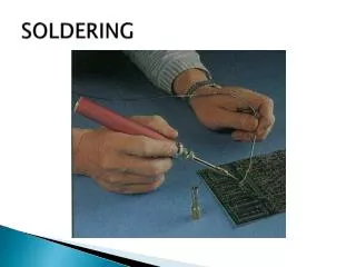
Start Soldering Hold the soldering iron like a pen, near the base of the handle. Don’t use the very tip of the iron but rather the side of the tip for the best heat transfer. Follow these steps: • Touch the soldering iron onto the joint to be made. Make sure it makes contact with both the component lead and the copper pad on the PCB. Hold the tip there for 1 to 3 seconds to heat it to the point it will melt solder. • Feed a small amount of solder onto the joint component lead and PCB pad under the tip of the iron (not directly to the tip of the iron). Apply just enough solder to form a volcano shape in the joint. • Remove the solder feed while continuing to apply heat, then remove the iron, taking care not to move the joint. • Let cool then inspect the joint closely. It should look shiny and have a volcano shape. If not then you will need to reheat it and try again.
Inspect The Solder Joint Once the solder joint has cooled you should inspect it to make sure it is a good joint. What you are looking for is a nice volcano shape that is smooth, bright, shiny, and clean. Here are some common bad joints that should be re-soldered: • Too much solder: This will look more like a ball than a volcano. This joint will actually be weaker than a proper joint and prone to failure as a result. • Too little solder: You will see gaps between the component and pads. This joint will not conduct electricity. • Cold solder joint: You will see lumps or a rough surface. This joint will be unreliable as it will form cracks over time. • Solder-Bridge/Short: This join connects more than one component. If this was intended then it is not a problem. However, if this was not intended then it will short the circuit.
De-Soldering If you need to correct a soldering mistake or remove a component, you will need to use a process called De-Soldering. Follow these steps: • Touch the soldering iron onto the joint to be un-made. Make sure it makes contact with both the component lead and the copper pad on the PCB. Hold the tip there for 1 to 3 seconds to heat it to the point it will melt the solder. • When the solder is in liquid form apply a de-solder wick (made of braided copper strands) to collect the solder off of the component and PCB. Optionally instead of using a de-solder wick you could use a solder-sucker tool to suck up the solder at the point it is in liquid form. • Remove the solder Iron from the joint and let the joint cool. • Remove the component or re-solder it in place again.
Practice Projects The best way to get good at something is to practice. Since soldering electronics has the potential to damage those electronics if done incorrectly it is best to practice initially on wires and PCBs without electrical components. Then you can progress to working on simple electrical circuits that are built specifically for solder practice. Finally, after practice, you will graduate to soldering on working electronics. We will present some initial soldering practice project suggestions here.
Practice Project One For this practice project you will simply be soldering the pads of a printed circuit board with no components. • Follow the soldering procedures previously outlined • Practice making good solder joints on a PCB pad with no components or wires in the joint. • This will make the solder joint look more like a blob than a volcano. Look for all the other aspects of a good solder joint such as smooth, bright, shiny, and clean. • Make sure the solder does not extend beyond the pad. • Also try making solder bridges that connect two pads.
Practice Project Two For this practice project you will simply be soldering wires to the pads of a printed circuit board. • Take several jumper wires and feed the bare ends of the wire through 2 holes of the PCB. • Follow the soldering procedures previously outlined • Practice making good solder joints on the PCB pads with wires in the joints. • Look for all the aspects of a good solder joint such as volcano shape, smooth, bright, shiny, and clean. • Make sure the solder does not extend beyond the pads. • Connect the wires together on one end using a solder bridge. You could also use part of one of the wires to cross the bridge.
Practice Project Three For this practice project you will be creating a simple circuit and soldering the components to the pads of a printed circuit board. • Use two jumper wires (or the two wires from a 9V battery connector), a resistor, and an LED to make the circuit. • Feel free to initially test this circuit on a solderless breadboard. • Following soldering procedures, solder all the components one at a time onto a PCB to form the circuit. • Each component or wire should use its own hole on the PCB. Use solder bridges between these holes to connect the components. • Look for all the aspects of a good solder joint such as volcano shape, smooth, bright, shiny, and clean. • Test your final circuit by connecting a 9V battery and look for the LED to light.
More Information This Presentation • http://solder.altbier.us/ Other Training by Richard Gowen (@alt_bier) • http://altbier.us/ How To Solder Videos • http://bfy.tw/El2D