Download
1 / 23
230 likes | 382 Views
SKA – The Reference Design. Peter Hall SKA International Project Engineer, ISPO www.skatelescope.org Next-Generation Correlators Workshop Groningen, June 28, 2006. Outline. SKA SKA R eference D esign Selected antenna technology Correlator matters (brief) Project news.

E N D
SKA – The Reference Design Peter Hall SKA International Project Engineer, ISPO www.skatelescope.org Next-Generation Correlators Workshop Groningen, June 28, 2006
Outline • SKA • SKA Reference Design • Selected antenna technology • Correlator matters (brief) • Project news
SKA At A Glance • Aperture synthesis radio telescope with 1 km2 of effective collecting area by 2020 • 1 km2 ~ 100 x VLA area • Limited gains by reducing receiver noise • Just need more microwave photons! • Frequency range 0.1 - 25 GHz • Large bandwidths (4 GHz), large fields-of-view (50 deg2) • New capabilities: area re-use (“multi-fielding”), RFI mitigation, high dynamic range imaging, …. • Innovative design to reduce cost • € 1000 per m2 target is about 0.1 current practice • International funding: ~ € 1 billion • 17-country international consortium • 4 potential sites; ranking in progress } Huge data rates & volumes
SKA Timeline Inter-governmental discussions including site selection ‘1% SKA’ Science Initial concept ‘10% SKA’ Science First SKA Working Group ISSC MoAs Science Case published Site short-listing SKA Complete { { { 92 96 0405 06 07 08 09 1014 18 22 { 2000 2000 { { { Feasibility study Concept exposition Optimise Design Define SKA System Phase 1 Build 10% SKA Full array Build 100% SKA Reference design selected Construct 1% SKA Pathfinders Radio interferometers can be built in stages (Inbuilt risk mitigation)
SKA: Radio Meets IT (Again) Is SKA a software telescope? Almost!
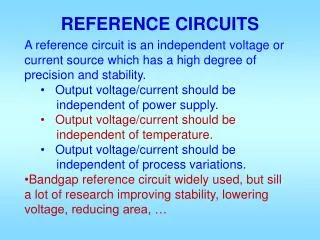
Reference Design - Background • Reference Design (RD) • Provides recognizable SKA image • Focuses science and engineering • Forms basis of SKA costing • Is a strong candidate for actual implementation • Result of wide exploration of design space • Original SKA concepts pushed boundaries in key areas: often simultaneously! • Brightness sensitivity, field-of-view, no. FOVs, frequency coverage, … • RD retains major precepts in each frequency range • All SKA concepts had/have much common system design • RD balances innovation and risk • Recognizes need to optimize within selected technology mix • Maps out technology contingencies • Fall-back positions at every decision point
SKA Reference Design • A sparse aperture array for 0.1 - 0.3 GHz (Low-Band) • “Era of Recombination” array • Super LOFAR, MWA etc • Multiple independent FOVs, wide FOVs • Low risk • A small dish + “smart feed” for 0.3 - 25 GHz • Radio camera • Dish ~ 10 m diameter • Smart feed wide response in angle OR frequency • Mid-Band0.3 – 3 GHz: wide FOV • High-Band 3+ GHz: wide bandwidth • Both low risk + high risk components • Driven in part by need for sensitive, wide FOV telescope a.s.a.p (SKA Phase 1) • An innovation path • Radio “fish eye” lens • Dense aperture array for 0.3 – 1 GHz • Independent FOV capability to 1 GHz • All-sky monitoring capability • High risk (but potentially high return) -----------------------------------------------------------------------------------------------------------------------
Reference Design Digitalradio camera Radio fish-eye lens + stations to 3000 km radio “fish-eye lens” Inner core Station
SKA – Schematically (About 150 stations) (About 2000 antennas – all correlated)
Reference Design: Some Technology > 3 GHz: wide-band feed High-Band Mid-Band 0.3 – 3 GHz: phased array feed Swinburne/CVA visualization Low-Band Innovation path: dense aperture array < 0.3 GHz: sparse aperture array
Small Dish + Phased Array Feed Phased array feed ~ l/D radian 10 m dish cost target: ~ €30k exc. feed Multiple fields FOV expansion factors ~30 may be practical D Correlator & further processing Digital beamformer Terminology: PAF is one type of Focal Plane Array
PAF Operation Key question: How calibratable are PAFs? D. Hayman, T. Bird, P. Hall
Reference Design Practicalities • Full frequency range unlikely to be affordable • Possible outcome: (EoR array) + (0.3 – 10 GHz) • Dense AA is least mature technology in cost terms • Balance between AA and SD collecting area will depend on cost and performance demonstration • AA probably has most scientific value as a central collecting area • But SD+PAFs also need rapid demonstration • Cheap dishes and astronomically-capable PAFs are not trivial • Low frequency efficiency is a potential issue • Ultimate contingency if AA, SD+PAF fail: • Super-LOFAR, 0.1 - 0.3 GHz, plus • “small” dishes (~10 m) + single pixel feed, > 0.3 GHz • 7 deg2 FOV at 0.7 GHz; “small” FOV partially compensated by better Aeff/Tsys • Large-scale cost – performance estimation begins Q4 ’06 • Closely allied with variational analysis wrt science goals • Strawman design for forthcoming Paris meeting
Wide Fields • Same FOV same no. of receiver chains • Concept independent (almost) • Many small antennas correlator intensive • Small dishes or AA patches • Fewer, larger antennas with FOV expansion reduced correlator load • Use focal plane beamforming to reduce order of correlation challenge • Bigger dishes + PAF (or larger AA patches) • Big question: does extra PAF calibration cost negate correlator saving? • Bigger antennas • Better low freq performance • More sensitive, easier to calibrate • Better RFI discrimination • Smaller antennas • Probably more attractive production costing • Easier to calibrate? • Low & mid-band wide-FOV operation fits within processing envelope defined by high band SKA spec.
SKA Correlator – Output Data Rate 4000 stations 4 polarizationproducts 2x16-bit fixed point numbers/complex value 128 MB per visibility set Integration time 0.1 sec 1000 spectral channels 10 station beams 9 TB/sec output data rate Need special purpose hardware for initial stages of post-correlation processing
SKA Correlator Attributes • Extreme flexibility • Simultaneous low, medium, high band operation • Complete trade-off of parameters (no. inputs, bandwidths, no. FOVs, processing accuracy, ….) • Support for “new” science: • High time resolution imaging, real-time VLBI, …. • Highly scaleable, reliable, maintainable, upgradeable • “Open telescope” ? ; standard data formats/interfaces (accept overheads) ; graceful degradation + hot spares operating model • Minimize NRE over life of telescope maximum re-useability • Station correlators can be modest • E.g. calibration to optimize station beamforming may not require full or continuous bandwidth coverage • Signal connection and routing will be a major issue • Power is a major issue (remote sites, minimize op cost) • Line between correlator and other DSP will be blurred • Line between DSP engines and computers will be blurred • SKA DSP will likely be a mix of ASIC, FPGA and computers
SKA – Many Other Challenges • Low-noise, integrated, receivers • E.g. millions-off for mid-band • High speed data transport • Looking for 100 Gb/s trans-continental and trans-oceanic • Signal processing • beyond just correlation (IM, tied array modes, …) • Post-processing • 2015-2020 computing capacity will limit initial science but cannot dominate system design • Archive and sharing of data will be a major challenge • Pathfinders and demonstrators are pivotal • Allen Telescope Array, LOFAR, xNTD, Karoo Array Telescope, DSNA, APERTIF, EMBRACE, 2-PAD …. • €200M committed so far; €80M explicitly for SKA; additional €40M expected in China shortly
SKA Engineering Philosophy • Strong emphasis on technology demonstration • Retire risk as early as possible • Focus on: • Aggressive cost reduction strategies (e.g. SKADS) • International collaboration & deliverables • Industry engagement • Pre-competitive R&D • Paradigm shift to deliver SKA on required timescales e.g. SD+PAF Demonstrator - NTD
Current SKA Happenings • Site assessment • RFI and other studies complete; list of “acceptable” or “qualified” sites soon • Funding agencies and SKA • Formed Inter-agency Working Group; continuing engagement • Funding opportunities (e.g. ESFRI) • Forthcoming Engineering – Science meeting • Paris, 4-8 Sept • Emphasis on Reference Design, project costing • International engineering review Q4/07 – Q1/08 • Reference Design, specifications, … • Continued science and engineering exposition • More outreach • New animations, telescope model, …. • More industry engagement • Major structural, governance implications • More inter-region collaboration • Easier as technology concepts coalesce
Summary • Site selection in progress • Reference Design identified • RD technologies being developed via regional pathfinders • Rapidly increasing inter-region collaboration • Initial SKA system design in progress • Incl. cost and performance modelling • Preliminary engineering reviews 2007-08 • Industry interaction increasing • SKA Phase 1 - start 2011