Download
1 / 29
310 likes | 469 Views
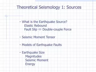
Fault plane solution and moment tensor inversion. J. Havskov. Main topics. Fault plane solution Use of polarities Use of polarities and amplitude ratios Regional moment tensor inversion using waveforms Practical demonstration. Focal mechanism parameters. Strike: Direction of the fault

E N D
Main topics • Fault plane solution • Use of polarities • Use of polarities and amplitude ratios • Regional moment tensor inversion using waveforms • Practical demonstration
Focal mechanism parameters Strike: Direction of the fault Dip: inclination of the fualt Rake/slip: direction of motion These parameters can be determined from earthquake data
Principle of fault plane solution First motion of P observed at different directions relative to the fault plane for a strike-slip fault. The 2 arrows in the fault plane show the relative slip direction in the fault plane.
Focal sphere The focal sphere is a small sphere centered on the hypocenter. The angle of incidence, i, is the angle at which the ray leaves the earthquake focus. It is measured from the vertical direction.
Typical fault plane solutions The two great circles which separates black (compression) and white (dilatation) show the orientation and the dip to the two possible fault planes of which the eartquake moved one of them
Typical fault plane solutions Focal meachnism solutions always give two possible faults for the rupture.
Focal meachnism and stress field The double couple can be represented compressional axis (P) and tensional axis (T)
Fps with polarities, not an exact science The left figure show possible solutions within a 5˚ grid and one polarity error and the figure to the left is one of the possible solutions. Compressions are indicated with circles and dilatation with triangles. The arrow in the right hand figure indicates the polarity that does not fit and the corresponding seismogram is shown at the bottom.
Radiation patteren also shows amplitude variation in addtion to polarity change 0 0 0 0 Amplitude is zero along the x and y-axis and maximum at 45 deg to them.
Amplitude variation Radiation pattern from a double couple source in the x1-x2 plane. (a) The spherical coordinate system, (b) and (c): The P wave radiation pattern, (d): The S wave radiation pattern. Figure b and the two figures in the middle show amplitude and the figures to the right show the direction of motion.
Amplitude variation global event Broadband seismograms of the vertical component showing P and S for a deep earthquake (260 km) near Japan. The three stations have similar distances but different azimuths (Az) as indicated on the figure. mb=6.7.
Amplitude variation local event A broadband (KONO) and a SP (SUE) seismogram of the vertical component of a local earthquake. The two stations have similar distances (167 – 173 km) but different azimuth (Az) as indicated on the figure. ML = 2.8.
Amplitude theory • F: source amplitudes as a function of strike, dip and rake • M: magnitude • A: attenuation • Amplitude observed F*M*A • 4 unknowns: M, strike, dip, rake • In theory 4 amplitudes needed • Non linear equation so solution by grid search
Amplitude ratios of rays going the same way • Using amplitude ratios, the effect of the path mostly cancels out • Ratio=F(strike,dip,rake)*(relative attenuation)*(relative free surface) • Only 3 parameters to determine (no moment) • More reliable than absolute amplitudes
Fps with amplitudes for a distant event Left: The focal mechanism determined by the GCMT moment tensor inversion together with 13 polarities. Middle: Focal mechanisms determined by using the 13 polarities, Right: Focal mechanism determined by using 13 polarities and 5 amplitude ratios from 3 stations. mb=6.7.
Strange fault plane solutions These fault plane solutions have been observed
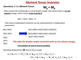
Moment tensor definition An arbitrary seismic source can be described by a combination of 9 force couples.
Moment tensor decomposition into 3 sources In a coordinate system where the moment tensor can be represented by a diagonal matrix, the moment tensor can be decomposed into the moment tensor of 2 fault plane solutions and an explosive source.
Non double couple fault plane solutions Example of two CLVD (compensated linear vector dipoles) seismic sources and their associated moment tensors
A good solution with polarities does not ensure that there is not a strong non double couple component. Focal solution for a small earthquake in the Hengill geothermal area on Iceland. Solution a) is made with polarities only Solution b) is the moment tensor solution made with polarities and amplitude ratios Figure from Julian et al. (1998).
Moment tensor inversion • Observations = (known Green’s function)*(moment tensor) • Green’s function is synthetic seismograms (or amplitudes) due to a point source at the observed distance. • If enough observations, the moment tensor can be obtained by a linear inversion. • The observations can be: • Amplitudes • Spectral levels as defined earlier • Seismograms of P • Seismograms of surface waves • Seismograms of the complete waveforms
Data for inversion • Need broad band data with good signal to noise ratio • A good model Example of original data (black) and synthetic data (red)
Conclusion Fault plane solution are the most important parameter for understanding the earthquake mechanism Fault plane solution can be determined by several methods using seismic data The most complete and reliable method is the moment tensor inversion scheme, but it can only be use for events with M>4