Download
1 / 49
490 likes | 492 Views
This study proposes a computational modeling approach to determine the integrated response of G-20 heads of state to the "New Euro" currency. The findings, which can be released today to properly cleared audience, aim to understand brain organization and function for scientific and clinical purposes.

E N D
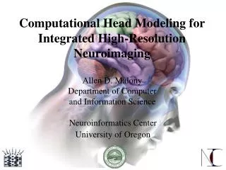
Computational Head Modeling for Integrated High-Resolution Neuroimaging Neuroinformatics Center University of Oregon Allen D. Malony Department of Computerand Information Science
New Euro and the G-20 Heads of State • Global economic crisis • G-20 meeting in London • Propose a global currency • Based on Euro model • “New Euro” (NEURO) • Obama concerned with acceptance • Reaction from G-20 Heads of State • Can not be just $ + € • NSA-funded “hidden” study • Build computational models of Heads of G-20 • Determine integrated response to NEURO imagining • Can release findings today (properly cleared audience)
Who Am I? • Professor, Dept. Computer and Information ScienceDirector, Neuroinformatics CenterUniversity of Oregon • Ph.D., University of Illinois, Urbana-Champaign • Fulbright Research Scholar (The Netherlands, Austria) • Alexander von Humboldt Research Award • National Science Foundation Young Investigator • Research interests • Parallel performance analysis, high-performance computing, scalable parallel software and tools • Computational science, neuroinformatics
Neuroscience and Neuroinformatics • Understanding of brain organization and function • Integration of information across many levels • Physical and functional • Gene to behavior • Microscopic to macroscopic scales • Challenges in brain observation and modeling • Structure and organization (imaging) • Operational and functional dynamics (temporal/spatial) • Physical, functional, and cognitive operation (models) • Challenges in interpreting brain states and dynamics • How to create and maintain of integrated views of the brain for both scientific and clinical purposes?
Human Brain Dynamics Analysis Problem • Understand functional operation of the human cortex • Dynamic cortex activation • Link to sensory/motor and cognitive activities • Multiple experimental paradigms and methods • Multiple research, clinical, and medical domains • Need for coupled/integrated modeling and analysis • Multi-modal observation (electromagnetic, MR, optical) • Physical brain models and theoretical cognitive models • Need for robust tools • Complex analysis of large multi-model data • Reasoning and interpretation of brain behavior • Problem solving environment for brain analysis
NeuroInformatics Center (NIC) at UO • Computational science applied to human neuroscience • Tools to help understand dynamic brain function • Tools to help diagnosis brain-related disorders • HPC simulation, complex data analysis, medical services • Integration of neuroimaging methods and technology • Coupled measures and evaluation (EEG/MEG, MR, ERP) • Advanced statistical signal analysis (PCA, ICA) • Advanced image analysis (segmentation, anatomy) • Computational head modeling (electromagnetics, FDM) • Source localization modeling (dipole, linear inverse) • Internet-based capabilities for brain analysis services, data archiving, and data mining
NIC Organization • Allen D. Malony, Director • Don M. Tucker, Associate Director • Sergei Turovets, Computational Physicist • Bob Frank, Senior Data Analyst • Kai Li, Computer Scientist • Chris Hoge, Computational Software Engineer • Matt Sottile, Computer Scientist, CIS Department • Dejing Dou, Computer Scientist, CIS Department • Gwen Frishkoff, Neuro Scientist, Wisconsin Medical C. • Brad Davidson, Systems administrator • Adnan Salman, Ph.D. student, Computer Science • Jason Sydes, Ph.D. student, Computer Science
NIC Scientists/Students and Projects • Sergei Turovets, Ph.D., PhysicsPhysics-based computational models of human head tissues for developing electrical and optical probes of brain activity • Kai Li, Ph.D., Computer ScienceTissue segmentation of neurological images, cortical surface extraction of the individual brain, and brain visualization • Bob Frank, M.S., MathematicsStatistical analysis of neurophysiological recordings to separate brain from non-brain signals in scalp and source space • Chris Hoge, M.S., Computer ScienceComputational software development, high-performance signal analysis tools, application server environments, EEG and MRI databases, neuroinformatics workflow • Matt Sottile, Ph.D., Computer ScienceEEG data modeling methods for detecting spike and seizure • Dejing Dou, Ph.D., Computer ScienceData mining and ontologies • Gwen Frishkoff, Ph.D., Psychology, Wisconsin Medical CollegeAutomated component separation, ERP pattern classification, and neuro electromagnetic ontologies • Adnan Salman, Ph.D. student, Computer ScienceOptimization solutions for finding human head tissues conductivity • Jason Sydes, M.S. student, Computer ScienceEEG and MRI database development
Neuroinformatic Challenges • Dense-array EEG signal analysis and decomposition • Artifact cleaning and component analysis • Automatic brain image segmentation • Brain tissue identification • Cortex extraction • Computational head modeling • Tissue conductivity estimation • Source localization • Statistical analysis to detect brain states • Discriminant analysis • Pattern recognition • Electromagnetic databases and ontologies • HPC, data management, workflow, services delivery
Observing Dynamic Brain Function • Brain activity occurs in cortex • Observing brain activity requires • high temporal and spatial resolution • Cortex activity generates scalp EEG • EEG data (dense-array, 256 channels) • High temporal (1msec) / poor spatial resolution (2D) • MEG has similar features and concerns • MR imaging (fMRI, PET) • Good spatial (3D) / poor temporal resolution (~1.0 sec) • Want both high temporal and spatial resolution • Need to address source localization problem!!! • Find cortical sources for measured EEG signals
Brain Activity Sources in the Cortex • Scalp EEG activity is generated in the cortex • Interested in location, orientation, and magnitude • Cortical sheet constrains possible locations • Orientation is normal to cortical surface • Need to capture convoluted geometry in 3D mesh • From segmented MRI/CT • Address linear superposition
Source Localization • Mapping of scalp potentials to cortical generators • Signal decomposition (addressing superposition) • Anatomical source modeling (localization) • Source modeling • Anatomical constraints • Accurate head model and physics • Computational head model formulation • Mathematical constraints • Criteria (e.g., smoothness, coherence) to constrain solution • Current solutions limited by • Simplistic geometry • Assumptions of conductivities
Computational Head Models Source localization requires modeling Full physics modeling of human head electromagnetics Step 1: Head tissue segmentation Obtain accurate tissue geometries Step 2: Numerical forward solution 3D numerical head model Map current sources to scalp potential Step 3: Conductivity modeling Find accurate tissue conductivities Inject currents and measure response Step 4: Source optimization Create cortex dipoles / lead field matrix
Neuroanatomical Tissue Segmentation (K. Li, PhD) • Classify pixels in MR images • Difficulties • Image artifacts, convoluted shapeof cortex, inter-subject variations • Exploit various prior knowledge • Structural, geometrical,morphological, radiological • Core segmentation techniques • Relative thresholding for voxel classification • Morphological image analysis for brain extraction • Automated segmentation workflow and tool (BrainK) • Classify voxel types of entire image then extract brain
BrainK Results (K. Li, VISAPP 2006) • Competitive with all leading segmentation packages • BrainVisa, SPM5, Freesurfer, FSL • Evaluation with respect to simulated and real datasets • Compare with expert manual MR segmentation • Cerebral cortex and cerebral white matter BrainK
Cortical Surface Reconstruction (Li, MIAR 2006) • Performed after brain tissue segmentation • Use the marching cube isosurface algorithm • Guarantee topology correctness • Application to surface tessellation and dipole creation
BrainK Segmentation and Cortex Extraction workflow segmentation result parameters cortical surface visualization
Skull Warping • Skull atlas and T1 MRI (inputs) • Performed after brain extraction • Transformation sequences • Scaling the brain volume • Rigid: translation, rotation • Affine: translation,rotation, scaling, shearing • Deformation field-basedtransformation • For head model construction when individual skull unavailable • Implemented in BrainK Skull warping
Addressing Superposition: Brain Electrical Fields • Brain electrical fields are dipolar • Volume conduction through head • Depth and location indeterminacy • Highly resistive skull (CSF: skull est. from 1:40 to 1:80) • Left-hemisphere scalp field may be generated by a right-hemisphere source • Multiple sources superposition • Radial source Tangential sources • one and two sources varying depths
Head Model Theoretical/Computational Flow Governing Equations ICS/BCS Continuous Solutions Finite-DifferenceFinite-ElementBoundary-ElementFinite-VolumeSpectral Discretization System of Algebraic Equations Discrete Nodal Values TridiagonalADISORGauss-SeidelGaussian elimination Equation (Matrix) Solver Approximate Solution (x,y,z,t)J (x,y,z,t)B (x,y,z,t)
Modeling Head Electromagnetics (S. Turovets) • Given positions and magnitudes of current sources • Given geometry and head volume conductivity • Calculate distribution of electrical potential on scalp • Solve linear Poisson equation on in with no-flux Neumann boundary condition (Forward problem) • Inverse problem uses general tomographic structure • Given , current injection configuration, forward model • Predict scalp potential, calculate error (least square norm) • Search for global minimum using non-linear optimization
Forward Solution (Salman, ICCS 2005) • Finite difference method (FDM) representation • 1-to-1 match to MRI resolution, plus air around head • Assign conductivity value to each voxel, zero in air • Alternating Direction Implicit (ADI) Method • IBM p690 • C++ and OpenMP • fast matrix libraries 3-sphere approximationof human head tissues >65%efficiency
Modeling Head Electromagnetics with Anisotropy • Head volume conduction (isotropic Poisson equation) • Need to model tissue and skull anisotropy • With existing principal axes, the tensor is symmetrical with 6 independent terms: ij = ji • Numerical implementation so far dealt with the orthotropic case: ii are different, allother components of ij = 0, ij. • Complete anisotropic forward solver with arbitrary ij implemented (Turovets, ICCS 2009) ()=S in , - scalar function of (x,y.z) -() n = 0 on (ij)=Sin , ij - tensor function of (x,y.z) -ij() n = 0 on
Skull and Brain Anisotropy Parameterization Total number of unknowns for skull conductivity N = 1 + 2N t r • Linear relation betweenconductivity and diffusiontensor eigenvalues • Parameterization: = K (d - d0) MRI DT brain map (Tuch et al, 2001)
Conductivity Optimization • Correct source inverse solutions depend on accurate estimates of head tissue conductivities • Scalp, skull, brain, CSF, … • Design as a conductivity search problem • Estimate conductivity values • Calculate forward solution and compare to measured • Iterate until error threshold is obtained (global minimum) • Use electrical impedance tomography methods • Multiple current injection pairs (source, sink) • Conductivity search can be parallelized • Simplex method (ICCS 2005) • Simulated annealing (ICCS 2007) currentsource currentsink measurementelectrodes
bEIT Procedure 3D subject geometry CT-registered with MRI Individual subject CT is not required Sensor positions are acquired by photogrammetry system and registered with head model Finite difference method solution for particular set of tissue conductivities Search for conductivity solutions
Conductivity Scanning and Registration (EGI) • EGI geodesic sensor net integration • Scanning current injection hardware • EEG and bounded EIT data acquisition • EGI photogrammetry system • Machine vision for sensor position registration • EGI tool for validation, correction, and visualization
Conductivity Optimization Dynamics (ICCS 2005) • Simplexsearch • Four tissues: • scalp • CSF • skull • brain • 4-way searchparallelism • 8-way ADIparallelism 1mm3 resolution
Observation • Bad conductivity solutions lead to bad source solutions • Must include skull inhomogeneity • Differences in skull anatomy (dense, marrow, sutures, ...) • Differences in conductivity • Parcel up the skull into several homogeneous parts • Assign separate conductivity to each part • Eleven major bones in skull
Conductivity Search Complexity (ICCS 2007) • Mores tissues to model increases search complexity • Number of parameters in the inverse solver increase • Simplex search reaches performance limits quickly • 5 tissues: fails to converge in a practical time • 6 tissues: fails to converge at all! • Switch to simulated annealing for search optimization • Include skull inhomogeneity • Forward and inverse solution • Validate with 13 preset conductivity values • 11 skull, CSF, scalp, brain • SA is finds 11 head tissues successfully
ODESSI (A. Salman, Ph.D. thesis) • Open Domain-enabled Environment for Simulation-based Scientific Investigations
Domain Problems in Neuroscience for ODESSI • Scientific investigations • Verification • forward and inverse solvers (4-shell sphere) • grid convergence, time step, special step • Validation • phantoms, animal experiments, data from surgery • Uncertainty and sensitivity analysis • sensor position, injected current, tissue conductivities, … • Parameter sweep • Optimization, extract optimal parameters to fit the data • Comparative analysis • Data management • Geometry MRI/CT, current injection, results
Investigations in Conductivity Modeling • Forward solver • Parameter tuning • Time-step: controls the speed of reaching the steady state • Convergence tolerance: sets the level of convergence • Geometry resolution error assessment • High resolution (1mm), accurate but inefficient • Low resolution (2mm), efficient but less accurate
Investigations in Conductivity Modeling • Sensitivity Analysis • How the uncertainty in each electrode’s potential can be apportioned to uncertainties to inputs • Potentials at the electrodes is: • insensitive to variation in CSF tissues conductivity • highly sensitive to scalp and skull conductivities • sensitive to brain conductivity
Source Localization Modeling • Scalp EEG is a linear superposition of cortical activity • How to model cortical activity? • Equivalent dipole • Distributed dipoles • Distributed dipole (distributed source) model • Large number of active dipoles throughout cortex • Approximate with larger sample set • tessellate cortex with patches • create dipoles normal to cortex patch • Create large linear equation: Ax = b • x = dipole intensities and b = sensor measurements • Solve for dipole intensity
Lead Field Matrix Formulation • A is know as the Lead Field Matrix (LFM) • Construction • Tessellate cortex surfacewith patches of equal size • Find spatial center andcreate dipole normal tosurface (N dipoles total) • For each dipole, calculateforward surface potential • for highest surface resolution or just sensor locations • requires N forward solves • Once found, solving Ax=b can be fast • Must register sensors!
Electrical Geodesics, Inc. (EGI) GeoSource • Distributed source modeling • Based on Montreal MRI standard reference • Used to create approximate head model [1] dipole orientations visible in head model view [2] flatmap view
raw … … virtual services storage resources compute resources Computational Integrated Neuroimaging System
NIC Computational Services Architecture interfaceadaptors
Papers • A. Salman, S. Turovets, A. Malony, J. Eriksen, and D. Tucker, “Computational Modeling of Human Head Conductivity,” International Conference on Computational Science (ICCS), May 2005. (Best paper) • A. Salman, S. Turovets, A. Malony, V. Vasilov, “Multi-Cluster, Mixed-Mode Computational Modeling of Human Head Conductivity,” International Workshop on OpenMP (IWOMP), June 2005. • K. Li, A. Malony, and D. Tucker, “Automatic Brain MR Image Segmentation with Relative Thresholding and Morphological Image Analysis,” International Conference on Computer Vision Theory and Applications (VISAPP), Setúbal, Portugal, February 2006. • K. Li, A. Malony, and D. Tucker, “A Multiscale Morphological Approach to Topology Correction of Cortical Surfaces,” International Workshop on Medical Imaging and Augmented Reality (MIAR 2006), August 2006. • S. Turovets, A. Salman, A. Malony, P. Poolman, C. Davey, D. Tucker, “Anatomically Constrained Conductivity Estimation of the Human Head in Vivo: Computational Procedure and Preliminary Experiments,” Electrical Impedance Tomography (EIT), July 2006. • A. Salman, A. Malony, S. Turovets, and D. Tucker, “Parallel Simulated Annealing for Computational Modeling of Human Head Conductivity,” InternationalConference on Computational Science (ICCS), May 2007. (Best paper) • P. Poolman, R. Frank, and S. Turovets. “Modified Lock-in Detection for Extraction of Impressed EEG Signals in Low Frequency Bounded-EIT Studies of the Human Head,” International Congress on Image and Signal Processing (CISP), Vol.1 , pp. 174-183, 2008.
Papers • P. Poolman, S. Turovets, R. Frank, and G. Russell, “Instrumentation and Signal Processing for Low-frequency Bounded-EIT Studies of the Human Head,” IEEE 2008 Instrumentation and Measurement Technology, pp. 602-606, 12-15 May 2008. • S. Turovets, P. Poolman, A. Salman, A. Malony, D. Tucker, “Conductivity Analysis for High-Resolution EEG,” International Conference on BioMedical Engineering and Informatics (BMEI), Vol. 2, pp. 386-393, 2008. • Adnan Salman, Allen Malony, Sergei Turovets and Don Tucker. "On the Role of Skull Parcellation in the Computational Modeling of Human Head Conductivity", Electrical Impedance Tomography Conference, Paper 05, Dartmouth College, Hanover, New Hampshire, June 16-18, 2008. • Salman, S. Turovets, A. Malony and V. Volkov, “Multi-cluster, Mixed-mode Computational Modeling of Human Head Conductivity,” M.S. Mueller et al . (Eds): IWOMP 2005/2006, Lecture Notes in Computer Science 4315, Springer-Verlag, pp. 119-130, 2008. • A. Salman, A. Malony, M. Sottile, “An Open Domain-extensible Environment for Simulation-based Scientific Investigation (ODESSI),” International Conference on Computational Science (ICCS), May 2009. • V. Volkov, A. Zherdetsky, S. Turovets, A. Malony, “A 3D Vector-Additive Iterative Solver for the Anisotropic Inhomogeneous Poisson Equation in the Forward EEG Problem,” InternationalConference on Computational Science (ICCS), May 2009.