Download

1 / 27
270 likes | 393 Views
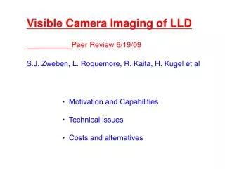
Movie clips are hyperlinked with this “camera” symbol. Fast Imaging of Visible Phenomena in NSTX. R. J. Maqueda Nova Photonics C. E. Bush ORNL L. Roquemore, K. Williams, S. J. Zweben PPPL. 47 th Annual APS-DPP Meeting October 24-28, 2005 Denver, Colorado Poster RP1.00014. Abstract

E N D
Movie clips are hyperlinked with this “camera” symbol. Fast Imaging of Visible Phenomena in NSTX R. J. Maqueda Nova Photonics C. E. Bush ORNL L. Roquemore, K. Williams, S. J. Zweben PPPL 47th Annual APS-DPP Meeting October 24-28, 2005 Denver, Colorado Poster RP1.00014
Abstract Edge phenomena are important for global plasma confinement as well as power and particle handling and distribution to plasma facing components. High frame rate, 2-D imaging is a powerful tool to access the physics behind these phenomena which include: edge turbulence and "blobs", ELMs, and MARFEs. This diagnostic is also useful in general plasma equilibrium and dynamics measurements, like those during Coaxial Helicity Injection discharges, and in pellet injection experiments. A new Phantom 7 fast-framing digital camera has been installed in NSTX which has been used at frame rates typically ranging between 68000 frames/s and 120000 frames/s and full discharge coverage (frames recorded for over 2 s). Examples will be presented showing the usefulness of this diagnostic for physics studies in the areas mentioned above. Work supported by DoE grant DE-FG02-04ER54520.
Outline Two-dimensional imaging at fast frame rates (>10000 frames/s) has many applications in magnetically confined plasmas: • Edge turbulence and “blobs”: Gas Puff Imaging (GPI) diagnostic. • L-H transitions: Where does the transition start? • Edge Localized Modes (ELMs): Heat pulse evolution and interaction with plasma facing components. • Multifaceted Asymmetric Radiation From the Edge: Is a MARFE axisymmetric? • Plasma positioning and equilibrium: Development of non-inductive current initiation by Coaxial Helicity Injection (CHI). • Lithium pellet injection: Ablation dynamics and plume development. A new fast framing camera capable of capturing 120,000 frames/s with full discharge coverage is being used in NSTX.
NSTX’s Phantom 7 Camera* • Frame rates of: ≤4,800 frames/s at 800 x 600 pixel resolution≤68,000 frames/s at 128 x 128 pixel resolution≤120,000 frames/s at 64 x 64 pixel resolution • Minimum frame exposures of 2 µs. • Digitization: 12-bit. • C-MOS detector with 30%-40% Q.E. and 22 µm x 22 µm pixels. • Full discharge coverage with 2 GB of on-board memory. • Fast download speeds through Ethernet connection (100 Mbit/s network). • Control through LabView, synchronized to MDS+ shot cycle. • Coherent fiber bundles used to transmit image to camera. • Interference filters used to select visible bands of spectrum. * Manufactured by Vision Research, Wayne, NJ.
GPI Diagnostic • Camera used to view visible emission from edge just above midplane. • Gas puff is injected to increase image contrast and brightness. Gas puff does not perturb local (nor global) plasma. • Emission filtered for Da light fromgas puff:I none f(ne,Te) • Da emission only seen in range ~ 5 eV < Te < 50 eV • View aligned along B field line to see 2-D structure B. Typical edge phenomena has a long parallel wavelength, filament structure. • For more details: “Gas puff imaging of edge turbulence”, R.J. Maqueda et al., Rev. Sci. Instrum. 74(3), p. 2020, 2003.
Summary of GPI ResultsOhmic H-mode • Edge turbulence observed during Ohmic H-modes in NSTX is similar to that measured in neutral beam heated H-modes. • Quiescent H-mode edge is present with the turbulence much reduced respect to the preceding L-mode phase. • Only small amplitude poloidal modulations of the emission has been observed during H-modes. • The fluctuation level decreases from a typical 10%-40% RMS level in L-mode to an also typical 5% RMS level in a quiescent H-mode. • The poloidal autocorrelation lengths appear to be somewhat smaller than those previously reported in H-modes (S.J. Zweben et al., Nucl. Fusion 44, p. 134, 2004). For details see: C. E. Bush, poster RP1.00028
GPI: L-H Transition Separatrix 24 cm radial ~11 MB 24 cm poloidal Antenna limiter shadow “Blobs” L-mode Spontaneous transition into quiescent H-mode Ohmic H-mode 0.65 ms mosaic D2 puff Da filter Transition takes place at ~192.1 ms
drsep = -5 cm L-mode burst drsep = 0 cm H-mode H-mode drsep =+5 cm GPI: Time Evolution Divertor Da (a.u.) 2 kHz “breathing” mode Image pixel (a.u.) Reduced fluctuation level during H-mode RMS fluctuation level Shot 115513 Time (s)
average 0.191 s - 0.192 s (L-mode) average 0.1922 s - 0.1932 s (H-mode) average 0.207 s - 0.208 s (H-mode) average 0.209 s - 0.210 s (L-mode) GPI: Radial Profiles Average image brightness (a.u.) RMS fluctuation level FWHM Poloidal auto-corr. length (cm) Shot 115513 Rmid-Rsep (m)
GPI: Active H-mode 24 cm radial Separatrix Antenna limiter shadow ~5.5 MB 24 cm poloidal Active “Blobs” Quiet 4.5 MW NBI Active Quiet 0.65 ms mosaic D2 puff Da filter H-mode edge with “blobs” ...micro-ELMs?
L-H TransitionWhere does the transition start? • The image intensity is consistently reduced first at the midplane near the center stack. • This is followed soon after (20-30 ms) by the outer divertor strike point. • The inner leg of the divertor region is delayed respect to the outer strike point by ~150 ms, with a slower decay rate.This, perhaps, introduced by atomic physics of highly radiating MARFE-like region. • NOTE: Data available for only LSN H-modes with high field side fuelling and fixed plasma parameters (800 kA, 4.5 kG, 4 MW NBI). • Only shots with “clean transitions” (no dithers and low fluctuation levels) were selected. • Time traces normalized to “1” before the transition and “0” after the transition
L-H Transition: Time Sequence Image intensity drop sequence: 1) Center stack near midplane, with tdrop~100 ms. 2) Outer divertor strike point, within 20-30 ms. 3) Other locations later, with slower decays. Similar sequence in Da light. Fish-eye view CII (657.8 nm) R.O.I. intensity (a.u.) Da Time (s)
Edge Localized Modes (ELMs) • Type I, III, and V ELMs are routinely seen in NSTX’s H-mode shots. (Type II ELMs have recently been observed too.) • Fast camera imaging shows evolution characteristics of impurity emission layers in divertor region during the different types of ELMs. • Type V ELMs show heat pulse propagation characteristics consistent with energy/particles ejection from the closed field line region near the lower strike point, low field side. (For more details see: R. Maingi, invited talk CI1b.003.) Lower divertor tangential view Phantom camera image
Type I ELM ~9.3 MB Unperturbed emission Energy/particle dump Recovery 0-600 scale 0-1568 scale Carbon sputtering 0-4095 scale Shot 117407 CII (657.8 nm) • Energy dump into divertor region causes CII emission layer to move to smaller (and larger) major radii. • EFIT reconstructions show the X-point moves upward and inward on the order of a few centimeters.
Type III ELM ~4.4 MB Outer strike point brightens 800 kA 4.2 MW NBI Double null Inner leg re-attaches Unperturbed emission Divertor Da (a.u.) 3 2 1 4 5 6 1 2 3 4 5 6 Shot 117432 Shot 117432 CII (657.8 nm) Modes on inner separatrix Recovery Relaxed to unperturbed emission Time (ms) • Energy dump affects inner leg detachment but emission layer persists close to separatrix. • There is no measurable movement of X-point.
Type V ELM ~4.8 MB Secondary band on outer strike point Heat pulse propagates on inner separatrix 800 kA 4.2 MW NBI LSN Unperturbed emission Divertor Da (a.u.) 3 2 1 4 5 6 Shot 117407 Shot 117407 1 2 3 4 5 6 CII (657.8 nm) Propagation continues ...and reaches X-point region Relaxed to unperturbed emission Time (ms) • Heat pulse propagates on inner separatrix, delayed from outer strike point band. • There is no measurable movement of X-point.
Type V ELM From peak in cross-correlation function: In-out delay = 0.32 ms Outer divertor Image intensity (counts) t = 255.477 ms Inner separatrix Shot 117407 Image intensity (counts) Shot 117407 Time (s)
Type V ELM: Heat Pulse Propagation 1.1 Km/s Slow down reaching X-point Poloidal distance along inner separatrix (cm) t = 255.587 ms Shot 117407 Shot 117407 Time (ms) peak in cross-correlation function
MARFE evolutionAre MARFEs toroidally symmetric? • MARFEs are seen on the divertor region and center stack of NSTX. • Although the evolution of the MARFE is varied, some new characteristics have been observed. • MARFEs born near the lower divertor move upward (against ion grad-B drift direction) as toroidally localized condensation, while rotating toroidally, following the magnetic field pitch. • Upward movement stagnates and becomes a “more typical” toroidally symmetric ring. • MARFE then moves downward towards lower divertor, while still rotating. • Presence of highly radiating MARFE coincides with decrease in divertor recycling. • MARFE: “Multifaceted Asymmetric Radiation From the Edge” [B. Lipschultz et al, Nucl. Fusion 24, p. 977, 1984].
MARFE evolution ~3.8 MB Fish-eye view Toroidally localized, rotating condensation Upper divertor Center stack Lower divertor Ion grad-B drift Stagnation 900 kA 6.4 MW NBI Double null MARFE moves downward 1.0 ms mosaic Da filter 9 ms exposures contrast enhanced
Plasma Positioning and EquilibriumCoaxial Helicity Injection (CHI) • Solenoid-free plasma startup is important for the spherical torus concept. Coaxial Helicity Injection (CHI) is a promising method to achieve this goal. • Fast-framing digital camera gives operators feedback on plasma positioning and equilibrium during CHI experiments. • 60 kA of closed flux current generated using only 7 kJ of capacitor bank energy. • In some discharges, the current channel shrinks to a small size and persists for more than 200 ms. For details see: R. Raman, contributed oral GO3.00011 R. Raman (U. Washington)
Coaxial Helicity Injection (CHI) Discharge evolution ~4.5 MB Fish-eye view No filter 9 ms exposures Detached plasma Plasma current (kA) Decay Fully grown plasma Breakdown and growing plasma Current persistence Injector current (kA) Fast crowbar Shot 118342 Time (ms) For details see: R. Raman, contributed oral GO3.00011
Lithium Pellet Injection • Lithium pellet injection is used in NSTX to modify the conditions of plasma facing components, as well as, for diagnostic purposes. • Lithium pellets with masses between 0.43 mg and 5 mg are injected just above the outer midplane at ~150 m/s. • Fast-framing digital camera shows pellet penetration, ablation of pellet material and transport along field lines towards divertor regions. • Ablated pellet material shows structure of underlying electron density (filamentary structure) and flux surfaces (if deep penetration). For details on lithium pellet injection experiments see: H. Kugel, contributed oral GO3.00008
Lithium Pellet Injection NBI Heated H-mode ~4.5 MB Fish-eye view Ablation begins in SOL Pellet material “diverted” Pellet material burns-out Filamentary structure Pellet material deposited on divertor surfaces 0-255 scale 0-1023 scale 0-4095 scale Shot 117909 LiII (548.5 nm) Pellet injection ~1.4 ms <-> ~20 cm penetration 600 kA - 4.4 MW NBI - double null
Lithium Pellet Injection Ohmic Helium Plasma Full penetration ~7.7 MB Fish-eye view Core flux surfaces Inside edge Outer edge 0-600 scale 0-1568 scale 0-4095 scale Shot 117094 LiII (548.5 nm) Flux surface Flows? Pellet ablation first seen at 240.47 ms 500 kA - Ohmic – inner wall limited
Summary of Physics Results • Ohmic H-modes in NSTX appear similar to neutral beam heated H-modes. They are categorized among the “quiescent” group of H-modes. • During the L-H transition (NBI shots), the recycling (and CII light) is first reduced at the midplane near the center stack and soon followed (20-30 ms) by the outer divertor strike point region. • Type V ELMs show heat pulse propagation characteristics consistent with energy/particle ejection from the closed field line region near the lower strike point, low field side. • MARFEs appear to originate as toroidally localized condensations that later become “more typical” toroidally symmetric rings.
Summary and Conclusions • Fast-framing visible cameras have multiple uses in magnetically confined plasmas. • Examples have been shown pertaining to edge turbulence, ELMs, L-H transitions, MARFEs, solenoid-free startup and pellet injection. • Other possible uses include:- ELMs using GPI and fish-eye views.- “GPI” using pellets and/or supersonic gas injector.- Interaction between MARFEs and ELMs. • With more than 210 Gbyte of Phantom camera data collected in the 2005 experimental campaign of NSTX the first challenge becomes automated analysis. (Note: Camera was used on only 1/3 of NSTX’s plasma shots.) • Nearly every short portion of data contains interesting, valuable information!