Download
1 / 2
20 likes | 115 Views
Original RF Feeds. Decoupler Elements. 30 MHz RF Power Sources. 5 Port Cubes. New Ground. RF Power (MW). 12 Antenna Straps. New Feeds. Previous Ground. Antenna Upgraded To Reduce Peak Voltages on the Straps. 0.188s. 0.418s. HHFW antenna extends toroidally 90º.

E N D
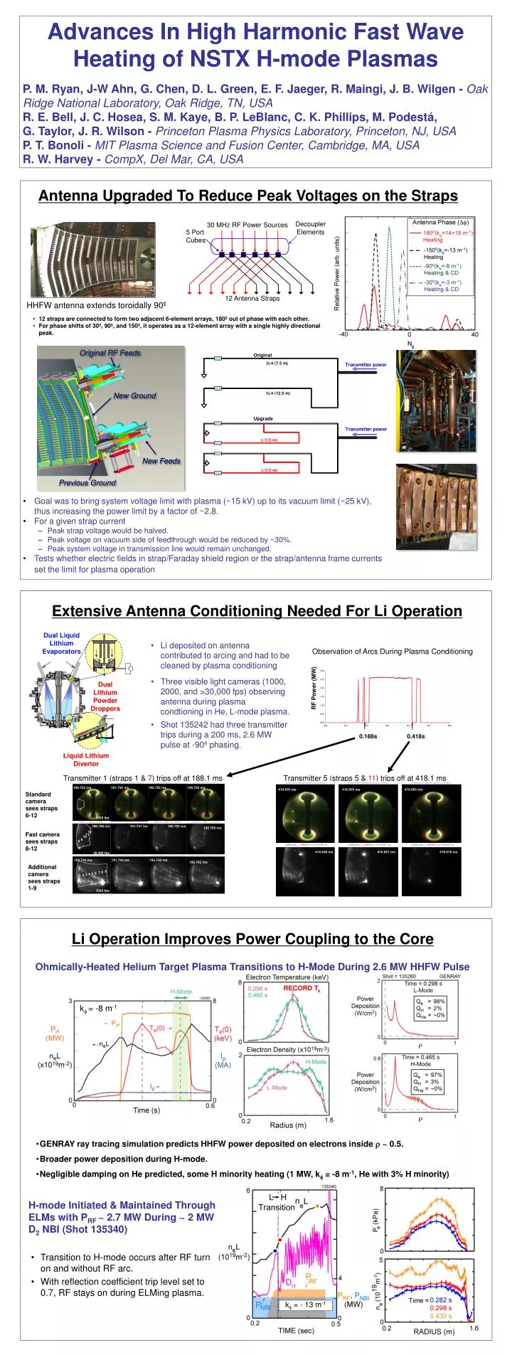
Original RF Feeds Decoupler Elements 30 MHz RF Power Sources 5 Port Cubes New Ground RF Power (MW) 12 Antenna Straps New Feeds Previous Ground Antenna Upgraded To Reduce Peak Voltages on the Straps 0.188s 0.418s HHFW antenna extends toroidally 90º • 12 straps are connected to form two adjacent 6-element arrays, 180º out of phase with each other. • For phase shifts of 30º, 90º, and 150º, it operates as a 12-element array with a single highly directional peak. • Goal was to bring system voltage limit with plasma (~15 kV) up to its vacuum limit (~25 kV), thus increasing the power limit by a factor of ~2.8. • For a given strap current • Peak strap voltage would be halved. • Peak voltage on vacuum side of feedthrough would be reduced by ~30%. • Peak system voltage in transmission line would remain unchanged. • Tests whether electric fields in strap/Faraday shield region or the strap/antenna frame currents set the limit for plasma operation Extensive Antenna Conditioning Needed For Li Operation Observation of Arcs During Plasma Conditioning • Li deposited on antenna contributed to arcing and had to be cleaned by plasma conditioning • Three visible light cameras (1000, 2000, and >30,000 fps) observing antenna during plasma condtioning in He, L-mode plasma. • Shot 135242 had three transmitter trips during a 200 ms, 2.6 MW pulse at -90º phasing. Transmitter 1 (straps 1 & 7) trips off at 188.1 ms Transmitter 5 (straps 5 & 11) trips off at 418.1 ms 189.755 ms 191.755 ms 193.755 ms 195.755 ms 414.655 ms 416.655 ms 419.655 ms Standard camera sees straps 6-12 2000 fps 189.749 ms 191.751 ms 193.753 ms kf = -8 m-1 195.755 ms 12 Fast camera sees straps 8-12 11 10 9 8 414.649 ms 416.651 ms 419.615 ms 38,460 fps 189.742 ms 191.742 ms 193.742 ms 195.742 ms Additional camera sees straps 1-9 9 8 7 6 5 4 3 2 1 1000 fps Li Operation Improves Power Coupling to the Core ~ Ohmically-Heated Helium Target Plasma Transitions to H-Mode During 2.6 MW HHFW Pulse RECORD Te • Dual Liquid Lithium Evaporators Dual Lithium Powder Droppers • GENRAY ray tracing simulation predicts HHFW power deposited on electrons inside r ~ 0.5. • Broader power deposition during H-mode. • Negligible damping on He predicted, some H minority heating (1 MW, k= -8 m-1, He with 3% H minority) H-mode Initiated & Maintained Through ELMs with PRF ~ 2.7 MW During ~ 2 MW D2 NBI (Shot 135340) Liquid Lithium Divertor • Transition to H-mode occurs after RF turn on and without RF arc. • With reflection coefficient trip level set to 0.7, RF stays on during ELMing plasma. kf = - 13 m-1 Advances In High Harmonic Fast Wave Heating of NSTX H-mode Plasmas P. M. Ryan, J-W Ahn, G. Chen, D. L. Green, E. F. Jaeger, R. Maingi, J. B. Wilgen - Oak Ridge National Laboratory, Oak Ridge, TN, USA R. E. Bell, J. C. Hosea, S. M. Kaye, B. P. LeBlanc, C. K. Phillips, M. Podestá, G. Taylor, J. R. Wilson - Princeton Plasma Physics Laboratory, Princeton, NJ, USA P. T. Bonoli - MIT Plasma Science and Fusion Center, Cambridge, MA, USA R. W. Harvey - CompX, Del Mar, CA, USA
-90° -90° 452 ms 455 ms 439.64 – 439.31 ms Electron Pressure Coupling Characteristics (0.353 sec) (PNB = 2 MW, IP = 1 MA,BT = 0.55 T) DWe ~ 13 kJ DWtot ~ 25 kJ kf = -13 m-1 Shot 130608 R. Harvey CompX DWe ~ 7 kJ DWtot ~ 14 kJ Results for HHFW Heating of NBI-driven H-modes RF-acceleration of fast ions from NBI Bay G IR view Bay I IR view BT(0) = 5.5 kG • Large increase in neutron rate when HHFW is applied to NBI plasmas (as predicted originally by CQL3D/GENRAY) • Measured significant enhancement & broadening of NBI fast-ions profile over a range of ion cyclotron harmonics and RF RF In NBI-driven H-mode, Power Coupling to Core Decreases ~20% Compared to L-mode • tDWtot ~ 20 ms gives heff ~ 66%, 40% for -150°, -90° antenna phasings • PRF losses coupled to edge are ~ 0.7MW, 1.1 MW for -150°, -90°, out of 1.8 MW launched by antenna • CQL3D simulation predicts ~ 40% of RF antenna power coupled to plasma for kf = -13 m-1 (-150º) Heating • Prf used in CQL3D modeling reduced to match simulated and measured neutron rate kf = -8 m-1 kf = -13 m-1 TRANSP/TORIC • TRANSP/TORIC modeling predicts RF absorption by NBI fast-ions lasts well after NBI turn off • All rf power absorbed by electrons prior to NBI pulse • After NBI turn-on, the fast-ion population absorbs HHFW power at the expense of the electrons • Trend confirmed by single time point calculations with AORSA, GENRAY and TORIC • RF Power Absorption by Fast-Ions Decreases as Fast-Ions Thermalize During RF-Heated NBI H-Mode • Electron b increases with time as density rises, increasing RF heating on electrons Visible & IR Images Show Significant RF Power Flows to Divertor, Particularly for Lower kfHeating Fast IR camera for studying ELM-resolved heat flux Visible Camera (with NBI-only light subtracted) ORNL IR Camera 3 Fast IR camera view Heat Flux(MW/m2) Pnbi = 2 MW Prf = 1.8 MW kf = - 8 m-1 Pnbi = 2 MW IR View • "Hot" region in outboard divertor more pronounced at k = –8 m-1than –13 m-1 • Linked along field lines to scrape-off plasma in front of antenna • 3 MW/m2 measured by IR cameraduring 2.6 MW of kf = –8 m-1 RF heating • Time for “hot” spot to decay away is ~ 20 ms at –8 m-1and ~ 8 ms at –13 m-1 Prf = 1.8 MW kf = -13 m-1 Pnbi = 2 MW Three bolometer views for studying divertor radiation • Summary • Antenna grounds were moved and power feeds added to reduce voltage on the straps. • Li wall conditioning, needed for improved power coupling through SOL, imposes additional antenna conditioning requirements. • Achieved record Te (>6 keV) in He. • H-modes accessed with HHFW alone. • Heating of core electrons in NBI-driven H-modes for k of 3, 8, 13 m-1. • Significant damping on the fast ions from neutral beams. • Increased edge plasma power losses in NBI-driven H-modes. • Increased heating of outer divertor with HHFW. RF heated pattern on lower divertor plate follows the change in magnetic field pitch