Download
1 / 17
170 likes | 396 Views
NSTX. Supported by . Update on high-speed infrared imaging of the NSTX divertor. College W&M Colorado Sch Mines Columbia U CompX General Atomics INEL Johns Hopkins U LANL LLNL Lodestar MIT Nova Photonics New York U Old Dominion U ORNL PPPL PSI Princeton U Purdue U SNL

E N D
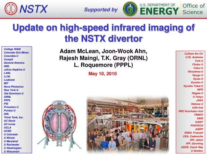
NSTX Supported by Update on high-speed infrared imaging of the NSTX divertor College W&M Colorado Sch Mines Columbia U CompX General Atomics INEL Johns Hopkins U LANL LLNL Lodestar MIT Nova Photonics New York U Old Dominion U ORNL PPPL PSI Princeton U Purdue U SNL Think Tank, Inc. UC Davis UC Irvine UCLA UCSD U Colorado U Illinois U Maryland U Rochester U Washington U Wisconsin Adam McLean, Joon-Wook Ahn, Rajesh Maingi, T.K. Gray (ORNL) L. Roquemore (PPPL) Culham Sci Ctr U St. Andrews York U Chubu U Fukui U Hiroshima U Hyogo U Kyoto U Kyushu U Kyushu Tokai U NIFS Niigata U U Tokyo JAEA Hebrew U Ioffe Inst RRC Kurchatov Inst TRINITI KBSI KAIST POSTECH ASIPP ENEA, Frascati CEA, Cadarache IPP, Jülich IPP, Garching ASCR, Czech Rep U Quebec May 10, 2010
Infrared measurements on NSTX • Essential for heat load measurement on plasma-facing components during plasma operation, especially in the divertor region • Heat flux calculated using 1-D conduction model into semi-infinite solid (2-D in collaboration with IPP Garching) • Transient heat load can exceed 10 MW/m2 • Localize hot spots and significant impurity sources • Use of the LLD in NSTX will make assumptions of high surface emissivity (applicable to graphite) inaccurate • Complications include: Surface coating changes in real time during plasma shots, emissivity changes due to H-absorption in Li, reflections from Li surface, deposition of Li on C surfaces, erosion/transport of Li and C • Two-color camera measures temperature based on the ratio of integrated IR emission in two IR bands, not single band intensity
Modifications required for dual-band IR adaptor • True-radial view into NSTX vessel • Adaptor able to be rotated to view 128x64 pixels in radial or toroidal direction • Camera mount redesigned to include: • ~12” extension to accommodate length of image splitter • Xeon-based PC operating camera moved outside of the test cell
Fast IR camera view into NSTX • IR view currently includes: • K-H LLD plate (operative) • H-E LLD plate (inoperative in early 2010) • Gap H bias tile (lithium-coated graphite, unheated) • CHI gap • Useful for study of LLD response to plasma • For remainder of 2010 • View rotated to include inner divertor, CHI gap, plus LLD plates • Better view of strike points in high-triangularity configuration
Primary dual-band IR adaptor components • Long-wave pass dichroic beamsplitter • Lambda Research Optics (CA, US) • Long-wave pass (7-10 μm transmit with Tavg~92%) • Medium-wave reflect (4-6 μm reflect with Tavg~99%) • Image splitter optical platform • CAIRN Research OptoSplit II (UK) • Extensively modified for operation in IR • Precision multi-axis optical alignment, focusing, flexibility • Lenses • Uncoated ZnSe meniscus input/output lenses (Tavg~60-70%) • To be replaced with broadband AR-coated diffractive optical elements (DOE) hybrid singlet lenses • 10X reduction in chromatic aberration, reduced spherical aberration, improved SNR • II-VI Infrared (PA, US) • Shortwave pass (SWP) and longwave pass (LWP) IR filters to limit spectral contamination in each channel • Reynard Corporation (CA, US) • Custom designed lens adaptors/mounts
Spectral throughput comparison for IR camera assembly • Comparison of static throughput losses due to optical components in the dual-band adaptor • Initial dual-band adaptor reduces throughput by ~4X compared to highest efficiency single-band mode • Near-term improvements will reduce the difference to ~2X • Significant margin is available in terms of integration time and dynamic range • Drop in transmission has no impact on required performance characteristics
Demonstrated application of dual-band IR with extensive ex-situ calibration Accomplished with SBFP camera + dual-band adaptor viewing a blackbody IR source Electro Optical Industries WS162 capable of up to 750°C 400+ frames of data taken with 10-75 μs integration time at 1610 Hz frame rate (1.6-12% duty cycle) Useful, low error LWIR/MWIR ratio from ~100-600˚C Altering IR camera system gain will be explored to see if the useful range of the ratio can be extended up to ~1000˚C 7
In-situ calibration accomplished during heating of the LLD • Data captured with dual-band camera viewing LLD plates at 20-320˚C • Each LLD plate contains 20 thermocouples embedded in their copper substrate, 5 of which are in positions in the view of the fast IR camera • Nearly 500 frames of data taken with 10-75 μs integration time for complete comparison to ex-situ calibration data • Signal in MWIR band (4-6 μm) reduced by 35-45% due to lack of AR-coating for this spectral band on ZnSe port window, plus dust/dirt/deposits • Signal in LWIR band (7-10 μm) also reduced 20-25% likely due to dust/dirt/deposits • Overall ~20% increase in LWIR/MWIR ratio compared to ex-situ data
Dual-band IR technique demonstrated on images taken during plasma operation in NSTX with heated LLD • Ex-situ calibration data of T vs. LWIR/MWIR ratio fitted to functional form, then shifted for best fit to available in-situ data • Data captured in ~350 shots so far, stored to MDSplus • Maximum 128x64 pixels on IR detector per channel (i.e., band), 1.6 kHz frame rate • In practice, limited to ~45-55 x 100-110 pixels to prevent channel overlap, and allow adequate background for subtraction • Data analyzed, temperature calibration applied using custom-designed IDL-based software
Pre- and post-shot sample data from April 7, 2010 • Data taken before plasma operation shows dual-band IR calibration is well matched to individual single-band calibrations • All three calibrations give proper temperature across K-H LLD plate, ~320˚C • Post-shot data shows dual-band indicates slightly higher temperature profile • Implies emissivity of lithium/lithium coated surface after a discharge is lower than during calibrations, possibly due to contamination of lithium by oxygen/carbon
Dual-band IR data during ELMing H-mode • Data taken during plasma operation shows consistently higher temperature from dual-band IR calibration compared to individual single-band calibrations • Implies emissivity of lithium/lithium coated surface is lower than during calibrations • LLD surface temperature reached ~600˚C during plasma exposure (K-H plate at 320˚C) • Filament structure from small ELMs (note: not turbulence filaments) clearly resolved, even better than either single-band • Analysis of frame-to-frame temporal continuity with limited/damaged detector in progress • Detailed analysis of temperature vs. time and heat flux to LLD (1-D and 2-D) can now proceed
Conclusions • Dual-band adaptor for the ORNL fast IR camera on NSTX successfully designed, built, calibrated and demonstrated • Components <15% of the cost of new dual-band IR camera, and does not limit the full frame-rate capability • Significant improvements in optical transmission and reduced chromatic aberrations will take place in short term • Will be used extensively for 1-D and 2-D heat flux measurements on LLD and lithium-coated graphite floor of NSTX • Dual-band adaptor may be easily optimized for SWIR/MWIR, or dual-color operation within the MWIR or LWIR bands • Platform allows interchange of beamsplitter and IR filters • Direct application to existing IR cameras at other fusion facilities (e.g., InSb camera with 3-4 and 4.5-5 μm colors, VO-based microbolometer camera with 8-10 and 10.5-12 μm colors)
ORNL IR system currently on NSTX • Two slow (30 Hz) IR cameras • Indigo Alpha/Omega, 30 Hz, 160x128 pixel uncooled microbolometer FPA, 3.4 x 3.7 x 4.8 cm • 7-13 μm, 12-bit, 0-700°C range, ZnSe window • First camera: 15° FOV of lower divertor, ~0.7 cm/pixel resolution • Second camera: 15° FOV of upper divertor, ~0.6 cm/pixel resolution • One fast (1.6-6.3 kHz) IR camera • Santa Barbara Focal Plane (Lockheed Martin) ImagIR 128x128, 40μm pixel HgCdTe FPA • QE>90% from 1.5-11 μm, 14-bit, <20 mK NETD • 25 mm f#2.3 Janos Varia (8-12 μm, Tavg=95%) and Ninox lenses (3-12 μm, Tavg=75%) • Bay H, 15.5° FOV of lower divertor, LN2-cooled, • 8-12 μm AR-coated ZnSe window
Two-color infrared camera • Installation of the LLD will make assumptions of low surface emissivity (applicable to graphite) inaccurate • Surface coating changes in real time during plasma shots, emissivity changes due to H-absorption in Li, reflections from Li surface • Two-color camera measures temperature based on the ratio of integrated IR emission in two IR bands, not on intensity of a single band • Image split into medium wavelength IR (4-6 μm) and long-wavelength IR (7-10 μm) using a dichroic beamsplitter, filtered with bandpass filters, projected side-by-side into the IR camera
Future plans for dual-band IR measurement on NSTX • Mini IR source to allow alignment/focus of system at Bay H port • PCMCIA CameraLink card, W-filament and LED IR sources • Broadband (BB) anti-reflection (AR) coated ZnSe window for port • >95% transmission from 3-11 μm would significantly improve dual-band SNR • Optical relay • Makes shielding of the camera against EMF interference, and neutron/gamma radiation possible • Extremely challenging for broadband IR (4-10 μm) due to chromatic aberrations • Investigating use of reflective optic design similar to JET/ITER design • Stepper-motor control of Bay H mirror orientation • Difficult to properly aim without in-situ IR source (heatable tile in 2011) • Moveable in-vessel protected mirror or IR fiber for window calibration with ex-situ IR source • UHV rotary feedthrough bakeable to 350°C (Lesker) • IR optical fiber limited to ~300˚C before devitrification