Download
1 / 25
270 likes | 579 Views
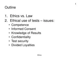
CHAPTER 8: MECHANICAL FAILURE. ISSUES TO ADDRESS. • How do flaws in a material initiate failure?. • How is fracture resistance quantified; how do different material classes compare?. • How do we estimate the stress to fracture?.

E N D
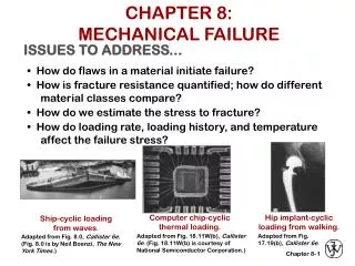
CHAPTER 8:MECHANICAL FAILURE ISSUES TO ADDRESS... • How do flaws in a material initiate failure? • How is fracture resistance quantified; how do different material classes compare? • How do we estimate the stress to fracture? • How do loading rate, loading history, and temperature affect the failure stress? Computer chip-cyclic thermal loading. Hip implant-cyclic loading from walking. Ship-cyclic loading from waves. Adapted from Fig. 18.11W(b), Callister 6e. (Fig. 18.11W(b) is courtesy of National Semiconductor Corporation.) Adapted from Fig. 17.19(b), Callister 6e. Adapted from Fig. 8.0, Callister 6e. (Fig. 8.0 is by Neil Boenzi, The New York Times.) 1
DUCTILE VS BRITTLE FAILURE • Classification: Adapted from Fig. 8.1, Callister 6e. • Ductile fracture is desirable! Ductile: warning before fracture Brittle: No warning 2
EX: FAILURE OF A PIPE • Ductile failure: --one piece --large deformation • Brittle failure: --many pieces --small deformation Figures from V.J. Colangelo and F.A. Heiser, Analysis of Metallurgical Failures (2nd ed.), Fig. 4.1(a) and (b), p. 66 John Wiley and Sons, Inc., 1987. Used with permission. 3
MODERATELY DUCTILE FAILURE • Evolution to failure: 50 mm 50 mm • Resulting fracture surfaces (steel) 100 mm particles serve as void nucleation sites. From V.J. Colangelo and F.A. Heiser, Analysis of Metallurgical Failures (2nd ed.), Fig. 11.28, p. 294, John Wiley and Sons, Inc., 1987. (Orig. source: P. Thornton, J. Mater. Sci., Vol. 6, 1971, pp. 347-56.) Fracture surface of tire cord wire loaded in tension. Courtesy of F. Roehrig, CC Technologies, Dublin, OH. Used with permission. 4
BRITTLE FRACTURE SURFACES • Intragranular (within grains) • Intergranular (between grains) 304 S. Steel (metal) Reprinted w/permission from "Metals Handbook", 9th ed, Fig. 633, p. 650. Copyright 1985, ASM International, Materials Park, OH. (Micrograph by J.R. Keiser and A.R. Olsen, Oak Ridge National Lab.) 316 S. Steel (metal) Reprinted w/ permission from "Metals Handbook", 9th ed, Fig. 650, p. 357. Copyright 1985, ASM International, Materials Park, OH. (Micrograph by D.R. Diercks, Argonne National Lab.) 160mm 4 mm Polypropylene (polymer) Reprinted w/ permission from R.W. Hertzberg, "Defor-mation and Fracture Mechanics of Engineering Materials", (4th ed.) Fig. 7.35(d), p. 303, John Wiley and Sons, Inc., 1996. Al Oxide (ceramic) Reprinted w/ permission from "Failure Analysis of Brittle Materials", p. 78. Copyright 1990, The American Ceramic Society, Westerville, OH. (Micrograph by R.M. Gruver and H. Kirchner.) 3mm 1 mm (Orig. source: K. Friedrick, Fracture 1977, Vol. 3, ICF4, Waterloo, CA, 1977, p. 1119.) 5
IDEAL VS REAL MATERIALS TS << TS engineering materials perfect materials • Stress-strain behavior (Room T): Reprinted w/ permission from R.W. Hertzberg, "Deformation and Fracture Mechanics of Engineering Materials", (4th ed.) Fig. 7.4. John Wiley and Sons, Inc., 1996. • DaVinci (500 yrs ago!) observed... --the longer the wire, the smaller the load to fail it. • Reasons: --flaws cause premature failure. --Larger samples are more flawed! 6
FLAWS ARE STRESS CONCENTRATORS! • Elliptical hole in a plate: • Stress distrib. in front of a hole: • Stress conc. factor: • Large Kt promotes failure: 7
ENGINEERING FRACTURE DESIGN • Avoid sharp corners! Adapted from Fig. 8.2W(c), Callister 6e. (Fig. 8.2W(c) is from G.H. Neugebauer, Prod. Eng. (NY), Vol. 14, pp. 82-87 1943.) 8
WHEN DOES A CRACK PROPAGATE? • rt at a crack tip is very small! • Result: crack tip stress is very large. • Crack propagates when: the tip stress is large enough to make: K ≥ Kc 9
GEOMETRY, LOAD, & MATERIAL • Condition for crack propagation: K ≥ Kc Stress Intensity Factor: --Depends on load & geometry. Fracture Toughness: --Depends on the material, temperature, environment, & rate of loading. • Values of K for some standard loads & geometries: Adapted from Fig. 8.8, Callister 6e. 10
FRACTURE TOUGHNESS increasing Based on data in Table B5, Callister 6e. Composite reinforcement geometry is: f = fibers; sf = short fibers; w = whiskers; p = particles. Addition data as noted (vol. fraction of reinforcement): 1. (55vol%) ASM Handbook, Vol. 21, ASM Int., Materials Park, OH (2001) p. 606. 2. (55 vol%) Courtesy J. Cornie, MMC, Inc., Waltham, MA. 3. (30 vol%) P.F. Becher et al., Fracture Mechanics of Ceramics, Vol. 7, Plenum Press (1986). pp. 61-73. 4. Courtesy CoorsTek, Golden, CO. 5. (30 vol%) S.T. Buljan et al., "Development of Ceramic Matrix Composites for Application in Technology for Advanced Engines Program", ORNL/Sub/85-22011/2, ORNL, 1992. 6. (20vol%) F.D. Gace et al., Ceram. Eng. Sci. Proc., Vol. 7 (1986) pp. 978-82. 11
DESIGN AGAINST CRACK GROWTH K ≥ Kc • Crack growth condition: • Largest, most stressed cracks grow first! --Result 2: Design stress dictates max. flaw size. --Result 1: Max flaw size dictates design stress. 12
DESIGN EX: AIRCRAFT WING • Material has Kc = 26 MPa-m0.5 • Two designs to consider... Design B --use same material --largest flaw is 4 mm --failure stress = ? Design A --largest flaw is 9 mm --failure stress = 112 MPa • Use... • Key point: Y and Kc are the same in both designs. --Result: 112 MPa 9 mm 4 mm Answer: • Reducing flaw size pays off! 13
LOADING RATE • Increased loading rate... --increases sy and TS --decreases %EL • Why? An increased rate gives less time for disl. to move past obstacles. • Impact loading: --severe testing case --more brittle --smaller toughness Adapted from Fig. 8.11(a) and (b), Callister 6e. (Fig. 8.11(b) is adapted from H.W. Hayden, W.G. Moffatt, and J. Wulff, The Structure and Properties of Materials, Vol. III, Mechanical Behavior, John Wiley and Sons, Inc. (1965) p. 13.) 14
TEMPERATURE • Increasing temperature... --increases %EL and Kc • Ductile-to-brittle transition temperature (DBTT)... Adapted from C. Barrett, W. Nix, and A.Tetelman, The Principles of Engineering Materials, Fig. 6-21, p. 220, Prentice-Hall, 1973. Electronically reproduced by permission of Pearson Education, Inc., Upper Saddle River, New Jersey. 15
DESIGN STRATEGY:STAY ABOVE THE DBTT! • Pre-WWII: The Titanic • WWII: Liberty ships Reprinted w/ permission from R.W. Hertzberg, "Deformation and Fracture Mechanics of Engineering Materials", (4th ed.) Fig. 7.1(a), p. 262, John Wiley and Sons, Inc., 1996. (Orig. source: Dr. Robert D. Ballard, The Discovery of the Titanic.) Reprinted w/ permission from R.W. Hertzberg, "Deformation and Fracture Mechanics of Engineering Materials", (4th ed.) Fig. 7.1(b), p. 262, John Wiley and Sons, Inc., 1996. (Orig. source: Earl R. Parker, "Behavior of Engineering Structures", Nat. Acad. Sci., Nat. Res. Council, John Wiley and Sons, Inc., NY, 1957.) • Problem: Used a type of steel with a DBTT ~ Room temp. 16
FATIGUE • Fatigue = failure under cyclic stress. Adapted from Fig. 8.16, Callister 6e. (Fig. 8.16 is from Materials Science in Engineering, 4/E by Carl. A. Keyser, Pearson Education, Inc., Upper Saddle River, NJ.) • Stress varies with time. --key parameters are S and sm • Key points: Fatigue... --can cause part failure, even though smax < sc. --causes ~ 90% of mechanical engineering failures. 17
FATIGUE DESIGN PARAMETERS • Fatigue limit, Sfat: --no fatigue if S < Sfat Adapted from Fig. 8.17(a), Callister 6e. • Sometimes, the fatigue limit is zero! Adapted from Fig. 8.17(b), Callister 6e. 18
FATIGUE MECHANISM • Crack grows incrementally typ. 1 to 6 increase in crack length per loading cycle crack origin • Failed rotating shaft --crack grew even though Kmax < Kc --crack grows faster if • Ds increases • crack gets longer • loading freq. increases. Adapted from Fig. 8.19, Callister 6e. (Fig. 8.19 is from D.J. Wulpi, Understanding How Components Fail, American Society for Metals, Materials Park, OH, 1985.) 19
IMPROVING FATIGUE LIFE 1. Impose a compressive surface stress (to suppress surface cracks from growing) Adapted from Fig. 8.22, Callister 6e. --Method 1: shot peening --Method 2: carburizing 2. Remove stress concentrators. Adapted from Fig. 8.23, Callister 6e. 20
CREEP • Occurs at elevated temperature, T > 0.4 Tmelt • Deformation changes with time. Adapted from Figs. 8.26 and 8.27, Callister 6e. 21
SECONDARY CREEP • Most of component life spent here. • Strain rate is constant at a given T, s --strain hardening is balanced by recovery stress exponent (material parameter) . activation energy for creep (material parameter) strain rate material const. applied stress Adapted from Fig. 8.29, Callister 6e. (Fig. 8.29 is from Metals Handbook: Properties and Selection: Stainless Steels, Tool Materials, and Special Purpose Metals, Vol. 3, 9th ed., D. Benjamin (Senior Ed.), American Society for Metals, 1980, p. 131.) • Strain rate increases for larger T, s 22
CREEP FAILURE • Failure: along grain boundaries. • Estimate rupture time S 590 Iron, T = 800C, s = 20 ksi g.b. cavities Adapted from Fig. 8.45, Callister 6e. (Fig. 8.45 is from F.R. Larson and J. Miller, Trans. ASME, 74, 765 (1952).) applied stress From V.J. Colangelo and F.A. Heiser, Analysis of Metallurgical Failures (2nd ed.), Fig. 4.32, p. 87, John Wiley and Sons, Inc., 1987. (Orig. source: Pergamon Press, Inc.) 24x103 K-log hr • Time to rupture, tr temperature function of applied stress 1073K Ans: tr = 233hr time to failure (rupture) 23
SUMMARY • Engineering materials don't reach theoretical strength. • Flaws produce stress concentrations that cause premature failure. • Sharp corners produce large stress concentrations and premature failure. • Failure type depends on T and stress: -for noncyclic s and T < 0.4Tm, failure stress decreases with: increased maximum flaw size, decreased T, increased rate of loading. -for cyclic s: cycles to fail decreases as Ds increases. -for higher T (T > 0.4Tm): time to fail decreases as s or T increases. 24
ANNOUNCEMENTS Reading: Core Problems: Self-help Problems: 0