Download
1 / 75
830 likes | 1.08k Views
BMFB 4283 NDT & FAILURE ANALYSIS . Lectures for Week 1 Prof. Qumrul Ahsan, PhD Department of Engineering Materials Faculty of Manufacturing Engineering. Issues to address. 1.0 Introduction to NDE 1.1 Definitions and Understanding of NDE 1.2 Concept of Defects and Discontinuity

E N D
BMFB 4283NDT & FAILURE ANALYSIS Lectures for Week 1 Prof. Qumrul Ahsan, PhD Department of Engineering Materials Faculty of Manufacturing Engineering
Issues to address 1.0 Introduction to NDE 1.1 Definitions and Understanding of NDE 1.2 Concept of Defects and Discontinuity 1.3 Visual Inspection
Non Destructive Evaluation (NDE) NDE is the examination of an object with technology that does not affect the object’s future usefulness Non destructive evaluation a term interchangeably with non destructive testing (NDT) NDT means The use of noninvasive techniques to determine the integrity of a material, component or structure or quantitatively measure some characteristic of an object. i.e. refers to technology that allows a component to be inspected for serviceability, without impairing its usefulness
Methods of NDT Thermography Visual Microwave Magnetic Particle Tap Testing X-ray Acoustic Microscopy Acoustic Emission Liquid Penetrant Magnetic Measurements Replication Ultrasonic Eddy Current Laser Interferometry Flux Leakage
Six Most Common NDT Methods • Visual • Liquid Penetrant • Magnetic • Ultrasonic • Eddy Current • X-ray
What are Some Uses of NDE Methods? • Flaw Detection and Evaluation • Leak Detection • Location Determination • Dimensional Measurements • Structure and Microstructure Characterization • Estimation of Mechanical and Physical Properties • Stress (Strain) and Dynamic Response Measurements • Material Sorting and Chemical Composition Determination Fluorescent penetrant indication
NDE - A Full Spectrum Technology There are NDE application at almost any stage in the production or life cycle of a component • Materials Development • To assist in product development Design NDE Technologies • Processing • To screen or sort incoming materials • Manufacturing • To verify proper assembly • In-Service Monitoring • To inspect for in-service damage
Common Application of NDT • Inspection of Raw Products • Inspection Following Secondary Processing • In-Services Damage Inspection
Inspection of Raw Products • Forgings, • Castings, • Extrusions, • etc.
Inspection Following Secondary Processing • Machining • Welding • Grinding • Heat treating • Plating • etc.
Inspection For In-Service Damage • Cracking • Corrosion • Erosion/Wear • Heat Damage • etc.
How is NDE Applied ? • Process or quality control into feedback control • Monitors the process • Feeds the sensor response back to the feedback controller • Controller controls the process variables • Process or quality control into accept/reject criteria • Inspects the finished product • “go” - > accept the product to perform service • “no go” -> reject the product ; reprocessed, recycled or scrapped
Understanding the NDE Choices • Physical nature of the material property or discontinuity to be inspected • Processes that govern NDE methods • Interaction of the probing field (or material) with the test material • The potential and limitations of available technology • Economic, environmental, regulatory, and other factors
How much do we inspect ? • Statistics • Consequences of Part Failure • Larger Systems or Safety-Critical parts • Retirement for cause • Risked-Informed Inspection
Definition of discontinuities • Discontinuity : An intentional or unintentional interruption in the configuration of the part • Flaw : A detectable lack of continuity or a detectable imperfection in a physical or dimensional attribute of a part • Defect : One or several discontinuities that do not meet specifications • Nonconforming : A part is deficient in one or more specified characteristics
Other important vocabularies • Indication : Observation of a discontinuity that requires interpretation e.g. cracks, inclusions, gas pockets • Interpretation : Determination whether an indication is relevant, nonrelevant or false • False : Indication not due to presence of defects in the test material or due to test procedure • Nonrelevant : An indication which has no relation to a discontinuity that is considered a defect in the part being tested • Evaluation :Assessment of a relevant indication to determine wether specifications of the serviceability of the part are met
Discontinuities & Defects • NATURE OF DEFECTS • Microscopic Defects • Macroscopic Defects • ORIGIN OF DEFECTS • Inherent Defects • Processing Defects • Service Defects • DETERIORATES PHYSICAL and MECHANICAL PROPERTIES of MATERIALS • DETECTION of DEFECTS • Destructive Testing • Non-Destructive Testing
Destructive Test Nondestructive Test • Advantages • Measurements are direct and • reliable • Quantitative measurements • Direct correlation between test • measurements and material • properties • Advantages • Tests are done directly on the • object • 100% testing on actual components • is possible • Many NDT methods can be applied • on the same part hence many or • all properties of interest can be • measured. • In-service testing is possible • Repeated checks over a period of • time are possible • Very little preparation is sufficient • Most test methods are rapid Table 1.0 Comparison of Destructive and Non-Destructive Tests
Destructive Test Nondestructive Test • Limitations • Tests are not made on the • objects directly. Hence need to • prove correlation between the • sample specimen used and • object • A single test may measure only • one or few of the properties • In-service testing is not possible • Measurement of properties over • a cumulative period of time • cannot readily be possible • Preparation of the test specimen • is costly • Time requirements are generally • high • Limitations • Measurements are indirect • Reliability to be verified • Qualitative measurements • Measurements can also be done • quantitatively • Skilled judgment and experience • are required to interpret indications Table 1.0 Comparison of Destructive and Non-Destructive Tests
CASTING DEFECTS : Inclusions • Inclusions are nonmetallic materials (oxides or sulphides) • a lower melting point than the metal • relative brittleness • these defects occur near the surface as a “skin” effect. • occur at the centre of the casting • they tend to be irregular in shape, not spherical or oval.
CASTING DEFECTS : Porosity • gas trapped in the molten metal • formed by • release from the molten metal itself • release from the green sand mold, water vapour, or turbulence caused when pouring the metal • form of small pockets or voids appears as round irregular or elongated shapes
CASTING DEFECTS : Shrinkage • Metal contracts or shrinks when changing from the liquid to the solid state and defects will occur in a casting unless sufficient molten metal is available to “feed” it. • Defects may take the form of cavities, branch-like tears • Shrinkage cavities occur usually at hot spots in the casting
CASTING DEFECTS • Hot Tears • If a section begins to shrink while still hot and there is not a sufficient supply of liquid metal, the resulting internal stress will tear the metal. This is because while hot the metal has relatively low strength • Piping : Central Cavity • As the casting solidifies, the metal contracts if there is not an adequate supply of molten metal to the centre of the casting • usually occurs in pure metals and alloys having narrow ranges of solidification temperature • causes lamination
Open Die Forging Defects Fracture - – exhausted ductility – Intergranular fracture in hot working • Barreling - Friction • Solution - – limited deformation per step – Process anneal between steps
Closed Die Forging Defects • Laps
Rolling Defects : Stringers • Nonmetallic inclusions in slabs or billets, that are thinned and lengthened in the direction of rolling, by the rolling process, are called stringers.
Other Processing Defects • Heat-Treated Cracks • Grinding Cracks
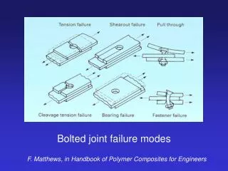
Weld Defects undercut • Groove in the base material • Result of improper welding technique (high travel speed, heat is too high) underfill • Groove in the weld material • Result of improper welding technique (inadequate filler material and high travel speed) • Excessive weld material (may not fuse to base) • Result of improper welding technique (welding travel speed is too slow) overlap
Weld Defects Incomplete root fusion or penetration Excessively thick root face in a butt weld Too small a root gap Arc (heat) input too low Large diameter electrode Small diameter electrode • In MMA welding, the risk of incomplete root fusion can be increased by using the incorrect welding parameters and electrode size to give inadequate arc energy input and shallow penetration.
Lack of side wall and inter-run fusion • Causes • too narrow a joint preparation • incorrect welding parameter settings • poor welder technique • magnetic arc blow • Insufficient cleaning of oily or scaled surfaces • “These types of imperfection are more likely to happen when welding in the vertical position” Lack of side wall fusion Lack of inter-run fusion
Weld Defects • Porosity : Causes • absorption of N, O, and H in the molten weld pool which is then released on solidification to become trapped in the weld metal. • N and O absorption in the weld pool usually originates from poor gas shielding. • H can originate from from inadequately dried electrodes, fluxes or the workpiece surface. Grease and oil on the surface of the workpiece or filler wire are also common sources of hydrogen. Distributed porosity Surface breaking pores
Weld Defects Slag inclusions Causes • Type of flux • Welder technique • Best practice • Use welding techniques to produce smooth weld beads and adequate inter-run fusion • Use the correct current and travel speed to avoid under-cutting the sidewall which will make the slag difficult to remove • Remove slag between runs paying particular attention to removing any slag trapped in crevices • Use grinding when welding difficult butt joints otherwise wire brushing or light chipping may be sufficient to remove the slag. Poor (convex) weld bead profile resulted in pockets of slag being trapped between the weld runs Radiograph of slag inclusions
Weld Defects Solidification cracking • Identification • Solidification cracks are normally readily distinguished from other types of cracks due to the following characteristic factors: • they occur only in the weld metal • they normally appear as straight lines along the centreline of the weld bead • as the cracks are 'open', they are easily visible with the naked eye • Causes • weld bead during solidification has insufficient strength to withstand the contraction stresses generated as the weld pool solidifies. Factors which increase the risk include: • insufficient weld bead size or shape • welding under high restraint • material properties such as a high impurity content or a relatively large amount of shrinkage on solidification
Weld Defects Hydrogen cracks in steels Crack along the coarse grain structure in the HAZ • Causes • There are three factors which combine to cause cracking: • hydrogen generated by the welding process • a hard brittle structure which is susceptible to cracking • residual tensile stresses acting on the welded joint • The effects of specific factors on the risk of cracking are: • weld metal hydrogen • parent material composition • parent material thickness • stresses acting on the weld • heat input
Outline • Introduction • Basic principles • Manual Vision Inspection • Human Vision • Common Inspection applications • Equipment • Automated or Machine Vision Inspection • Machine Vision • Common Inspection Applications • Equipment • Advantages and Limitations
Introduction • Visual inspection is commonly defined as “the examination of a material, component, or product for conditions of nonconformance using light and the eyes, alone or in conjunction with various aids”. • Visual inspection often also involves, shaking, listening, feeling, and sometimes even smelling the component being inspected. • Visual inspection consists of at least two major processes. • The first is a search process. • The second is a process of combining relevant knowledge, sensory input, and pertinent logical processes to provide an identification that some anomaly or pattern represents a flaw that poses a risk to the performance of the part. • Visual inspection is commonly employed to support other NDT methods. • Digital detectors and computer technology have made it possible to automate some visual inspections. This is known as “machine vision inspection.”
Introduction • The quality of an inspection are affected primarily by four factors. • The quality of the detector (eye or camera). • The lighting conditions. • The capability to process the visual data. • The level of training and attention to detail.
Introduction – Manual Versus Automated Inspection • The majority of visual inspections are completed by an inspector, but machine vision is becoming more common. • The primary advantage of an inspector is their ability to quickly adapt to a variety of lighting and other non-typical conditions, and their ability to use other senses. • The primary advantage of a machine vision inspection system is their ability to make very consistent and rapid inspections of specific details of a component. • Machine vision is primarily used in production applications where a large number of components require inspection and the inspection conditions can be closely controlled.
Basic Principles – Contrast Sensitivity • Contrast sensitivity is a measure of how faded or washed out an object can be before it becomes indistinguishable from a uniform field • It has been experimentally determined that the minimum discernible difference in gray scale level that the eye can detect is about 2% of full brightness • Contrast sensitivity varies with • the size or spatial frequency of a feature • The lighting conditions • Whether the object is lighteror darker than the background The graph to the right plots thevisibility of a spot as a function of theabove variables
Basic Principles –Light Intensity Measurement • Effective visual inspection requires adequate lighting. • The type of inspection will dictate the lighting requirements. Inspection of components with fine detail and low contrast will require greater illumination than components with large details and high contrast. • Light intensity may be measured with a suitable light meter. The unit of measure for white light is foot-candles (fc). • A foot-candle is equal to the amount of direct light thrown by one standard candle at a distance of 1 foot. • Inspection of components with fine detail and low contrast may require 100 foot-candles or more. • Specification requirements for lighting should be reviewed prior to performing an inspection.
Basic Principles –Light Directionality • The directionality of the light is a very important consideration. • For some applications, flat, even lighting works well. • For other applications, directional lighting is better because it produces shadows that are larger than the actual flaw and easier to detect.
Basic Principles –Optical Illusions Sometime the eye/mind has trouble correctly processing visual information. Are the horizontal lines parallel or do they slope? How many black dots do you see?
Basic Principles • For best results the inspector or machine vision operator must have: • A basic knowledge of material processing, forming, machining and joining processes. • A general understanding of design features, application and service requirements. • Specific instructions on what to look for and specific accept/reject criteria.
Inspection Applications Applications for visual inspection and many and range from looking a product over for obvious defect to performing detailed inspections. Some of the common applications include: • Detection of surface anomalies such as scratches, excess surface roughness, and areas void of paint or plating. • Crack, porosity, corrosion or other flaw detection. • Dimensional conformance. • Precision measurements. • Foreign object detection. • Component location.
Inspection Applications –Flaw Detection • Visual inspection of manufactured materials and components is a cost effective means of identifying flaws. • Visual inspection of a casting reveals a crack between a threaded opening and a pressed fit. • The aluminum sand casting has hot tears and shrinkage at the transition zones.
Inspection Applications – Flaw Detection In-service inspections of existing components and structures is commonly accomplished visually. • In this example, visual inspection of a fire escape reveals a failure in a handrail tube. • The failure is in the tube seam and is likely the result of ice expansion.
Inspection Applications – Flaw Detection Normal inspection practices for highway bridges rely almost entirely on visual inspection to evaluate the condition of the bridges.
Inspection Applications – Flaw Detection Over 80 percent of all aircraft inspections are performed visually.
Inspection Applications – Flaw Detection • Weld quality requirements are commonly determined through visual inspection. • Many standards have established acceptance criteria for welds. Transverse weld crack Slag rolled into toe of weld