Download
1 / 25
260 likes | 451 Views
Neutron Radiography and Tomography Facilities at NIST to Analyze In-Situ PEM Fuel Cell Performance. Facility Staff David L. Jacobson Daniel S. Hussey Elias Baltic Muhammad Arif Physics Laboratory Project Design Engineer James LaRock Center for Neutron Research. Fuel Cell Partners

E N D
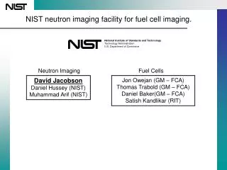
Neutron Radiography and Tomography Facilities at NIST to Analyze In-Situ PEM Fuel Cell Performance Facility Staff David L. Jacobson Daniel S. Hussey Elias Baltic Muhammad Arif Physics Laboratory Project Design Engineer James LaRock Center for Neutron Research Fuel Cell Partners Jon Owejan Jeffrey Gagliardo Thomas Trabold General Motor Fuel Cell Activities National Institute of Standards and Technology Technology Administration U.S. Department of Commerce Neutron Imaging Facility: http://physics.nist.gov/MajResFac/NIF/index.html
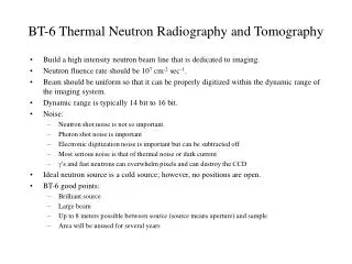
Old Facility • Began operation in 2003 • Located at BT-6 • Facility was small • Volume 3 m3 • Basically no support for fuel cell experiments other than • Hydrogen gas 1.2 slpm • Nitrogen from bottle • Air from bottle • Ceased operation in December of 2005 Neutron Imaging Facility: http://physics.nist.gov/MajResFac/NIF/index.html
New Facility • First users February 27, 2006 • Located at BT-2 • Much bigger 30 m3 • House gases/fluids • Hydrogen (18.8 slpm) • Oxygen (11.1 slpm) • Nitrogen • Air • Deionized water • Chilled water • Freeze chamber for low temperature testing (-40 oC) available early 2007 • Fuel cell test stands available and supported by NIST staff Neutron Imaging Facility: http://physics.nist.gov/MajResFac/NIF/index.html
Hydrogen Safety • Computational Fluid Dynamics modeling • Free software • NIST Fire Dynamics Simulator (FDS) • http://www.fire.nist.gov/fds/ • Release point in reactor confinement building • Extremely high buoyancy turbulently mixes hydrogen resulting in low concentrations throughout room Hydrogen Plume 22.4 lpm Neutron Imaging Facility: http://physics.nist.gov/MajResFac/NIF/index.html
Lower flammability limit Upper flammability limit Modeling the Release Point • Maximum release modeled for 22.4 liters per minute (2 g H2). • Very seldom is this release rate actually required. • Above release point a maximum of 68 mg of hydrogen is expected to be within the range of 77% to 4% and so an unlikely detonation of such a mixture is expected to have a maximum explosive yield similar to a few firecrackers. • Conclusion: for our system it is safe to release hydrogen to the room. Neutron Imaging Facility: http://physics.nist.gov/MajResFac/NIF/index.html
Modeling Hydrogen Release in Reactor Confinement Building Mass (kg/kg) x 10-4 Neutron Imaging Facility: http://physics.nist.gov/MajResFac/NIF/index.html
Schematic of New Facility Neutron Imaging Facility: http://physics.nist.gov/MajResFac/NIF/index.html
Design of Neutron Collimation Primary collimator • Primary collimator tapers beam • Bismuth filter • 15 cm long • Liquid nitrogen cooled • Apertures • 5 positions • Local shutter • Heavy concrete filled • 60 cm in length • 3 through tubes for additional collimation • Fast exposure control • Allows < 1 second exposure control Bismuth filter Apertures Local shutter Fast exposure Neutron Imaging Facility: http://physics.nist.gov/MajResFac/NIF/index.html
Primary Collimator • Hollow steel frame • Filled with heavy concrete • 10 cm long steel rings taper beam down to 2 cm maximum aperture size • Borated aluminum discs are used throughout to reduce long term activation Heavy concrete filled Steel case Steel rings taper beam from reactor Neutron Imaging Facility: http://physics.nist.gov/MajResFac/NIF/index.html
Bismuth Filter • Bismuth crystal • Filters gammas and high energy neutrons • Ideally single crystal • H ere we have several large single crystals • 5 cm reduces thermal neutrons by 57 % • 15 cm reduces neutron fluence to 19 % • Banjo Dewar • Provides insulated liquid nitrogen jacket • Sealed and evacuated during operation Banjo Dewar (named after the musical instrument) Super insulation/liquid nitrogen jacket 10 cm dia. hole for bismuth to sit Neutron Imaging Facility: http://physics.nist.gov/MajResFac/NIF/index.html
Aperture Assembly • Can be any material that fits • 5 positions • Largest aperture diameter is 2 cm due to primary collimation • Easily changed without major shielding manipulations 5 apertures (2 cm, 1.5 cm, 1.0 cm, 0.5 cm, 0.1 cm) Neutron Imaging Facility: http://physics.nist.gov/MajResFac/NIF/index.html
Rotating Drum • Rotates to 1 of 4 positions • Position 0 beam is blocked • Position 1 beam is collimated for 1 cm effective aperture • Position 2 beam is collimated for 2 cm effective aperture • Position 3 no collimation currently • Filled with heavy concrete • 60 cm long Neutron Imaging Facility: http://physics.nist.gov/MajResFac/NIF/index.html
Fast Exposure • Designed to ensure uniform fluence. • Beam is opened and closed in the same direction Neutron Imaging Facility: http://physics.nist.gov/MajResFac/NIF/index.html
Fast Exposure • Designed to ensure uniform fluence. • Beam is opened and closed in the same direction • Time for each motion is about 0.1 seconds. • Can be set for fixed times and manually operated • Can be operated by computer control. Neutron Imaging Facility: http://physics.nist.gov/MajResFac/NIF/index.html
Shielding • Steel shot and wax external to the reactor. • Inside reactor only heavy concrete and steel is used. Neutron Imaging Facility: http://physics.nist.gov/MajResFac/NIF/index.html
Schematic of New Facility Neutron Imaging Facility: http://physics.nist.gov/MajResFac/NIF/index.html
Flight Path and Sample Position • 6 meters from aperture to sample position. • Aluminum flight tube evacuated. • Short sections can be made into a shorter tube for closer positions. • Closest position is 1 meter. Neutron Imaging Facility: http://physics.nist.gov/MajResFac/NIF/index.html
Real-Time Detector Technology Front view Side view • Amorphous silicon • Varian Paxscan 2520 high energy version • Cost is ~$100,000.00 US • No longer produced as of 2006 • However, if you are willing to void the warranty you could convert a low energy detector (still produced) to a high energy detector. • Radiation hard • High frame rate (30 fps) • 127 micron spatial resolution • No optics – scintillator directly couples to the sensor to optimize light input efficiency • Standard green Li6ZnS scintillator 0.3 mm thick • We experienced a failure of the readout electronics in July of 2006 • Failure is believed to be due to radiation damage • We were able to quickly fix by swapping the guts of a spare low energy panel with this detector frame. • Data rate is 42 Megabytes per second (160 gigabytes per hour) Neutron beam Scintillator aSi sensor scintillator Readout electronics aSi sensor Neutron Imaging Facility: http://physics.nist.gov/MajResFac/NIF/index.html
New High Resolution Imaging Device • 25 micrometer resolution available this fall. • An order of magnitude improvement in spatial resolution. • 10 micrometer resolution expected in 2007. • Less than 10 micrometer??? Neutron Imaging Facility: http://physics.nist.gov/MajResFac/NIF/index.html
Beam Properties At 6 m • A factor of 2 in beam fluence rate can be gained by removing 5 cm of bismuth Neutron Imaging Facility: http://physics.nist.gov/MajResFac/NIF/index.html
Schematic of New Facility Neutron Imaging Facility: http://physics.nist.gov/MajResFac/NIF/index.html
Beam Stop 45 cm • With most intense beam the field is less than 0.2 mrem hr-1 or 2 Sv • Magnesium is used instead of aluminum to avoid harsh 7 MeV gamma from aluminum • Box of boron carbide 15 cm thick absorbs majority of beam • The rest is wax and steel shot 90 cm Neutron Imaging Facility: http://physics.nist.gov/MajResFac/NIF/index.html
Hydrogen Systems • State of the art, custom-built, PEFC test stand • Flow control over H2, Air, N2, He, O2 with accuracy of 1 % full scale: • H2: 0-500 and 0-3000 sccm • N2: 0-2000 sccm • Air: 0-100, 0-500, 0-2000, 0-8000 sccm • O2: 0-500, 0-5000 sccm • He: 0-600, 0-6000 sccm • Users can create custom gas mixtures for anode and cathode in the stand • Measurement of high current densities with boost power supply allowing voltage control of the cell to a minimum of 0.01 V • Heated Inlet gas lines • Built-in humidification of anode and cathode gas streams for all flow rates • Graphical User Interface • Logs and stores files of all cell parameters during operation • Multiple thermocouple inputs • Interfaced with facility hydrogen safety system • All users of the NIST NIF have access to the stand Neutron Imaging Facility: http://physics.nist.gov/MajResFac/NIF/index.html
Hydrogen Systems Continued • Piping manifold appears in back. • Nitrogen gas supplied from liquid nitrogen dewar. • Hydrogen generator provides 18.8 liters per minute. • Deionized water for the hydrogen generator and test stand humidifiers. Nitrogen Hydrogen Deionized water Hydrogen and Oxygen Sensor readout Neutron Imaging Facility: http://physics.nist.gov/MajResFac/NIF/index.html
Final Remarks • Facility is accepting proposals through the NIST user proposal system as well as proprietary requests directly to NIST staff. • Users from both industry, national laboratories and academia use the facility for both proprietary and non-proprietary research. • Reactor cycle is 290 days per year currently all have been utilized. Neutron Imaging Facility: http://physics.nist.gov/MajResFac/NIF/index.html