Download
1 / 47
470 likes | 511 Views
Research project on enhancing GPU architecture for real-time radiosity with rendering methods like rasterization, ray tracing, and radiosity. Implementing a GPU simulator for 3D graphics. |

E N D
3D Graphics Processor Architecture Victor Moya
PhD Project • Research on architecture improvements for future Graphic Processor Units (GPUs). • Design and implement a GPU simulator for 3D graphics. • Goal: • Real-Time radiosity on GPU.
Outline • Rendering. • Global Illumination. • Ray Tracing. • Radiosity. • Status.
Outline • Rendering. • Global Illumination. • Ray Tracing. • Radiosity. • Status.
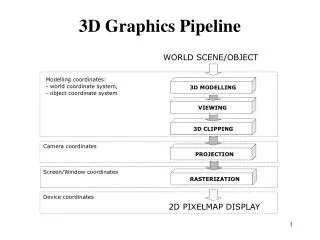
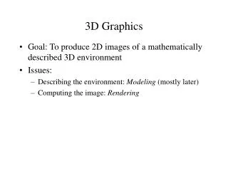
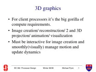
Rendering • Display a database of 3D objects over a screen, a picture (file) or a movie (file). • Rendering methods for 3D graphics: • Rasterization. • Reyes. • Raytracing. • Radiosity.
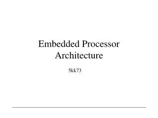
Rasterization • Project 3D polygons into a view plane. • Rasterize those polygons into fragments. • Shade the generated fragments. • Apply and combine textures to calculate the fragment color. • Objective: • Real-time. • Make it look as realistic as possible. • Avoid simulation of physical light behavior. • With the help of vertex and fragment shaders can render realistic images.
project polygons projection (near) plane rasterize polygons far plane
Reyes • Reyes or Renderman is a rendering architecture designed for realistic offline rendering. • The 3D objects are reduced to a number of micropolygons. • Micropolygon: polygon smaller than a pixel. • The micropolygons are then shaded and later sampled and written to the framebuffer. • Can be combined with raytracing, radiosity or other global illumination techniques.
Model Dice Shade Sample Visibility/Filter Image
RayTracing • Project a ray from the camera (framebuffer) to the objects in the scene. • Secondary rays may be created as reflections and refractions of the primary rays or other secondary rays. • Rays may be sent from the light sources to create caustic light effects. • Good simulation of reflection and transparency (refractions).
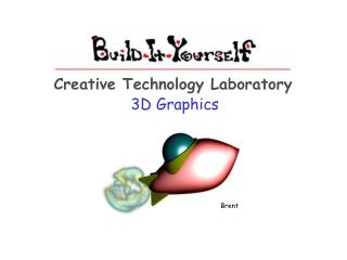
Radiosity • Simulates the physical behavior of the light. • Define the emission, reflection, refraction, absorption and scattering properties of the scene surfaces. • Mathematical formulation: system of linear equations. • Build iteratively an approximation to the illumination solution. • Used to implement global illumination • Diffuse lightning. • Indirect lightning.
16th pass 1st pass 2nd pass 3rd pass 4th pass
Real-time. Implemented on current hardware. Optimized for large polygons and small number of polygons Global illumination: Emulated using: Shaders Shadow maps. Stencil shadows. Off-line rendering. Implemented by software renderers. Optimized for large number of polygons. Global illumination: Shaders. Raytracing. Radiosity. Rasterization VS Reyes
Real-time. Implemented on current hardware. Optimized for large polygons and small number of polygons Global illumination: Emulated using: Shaders Shadow maps. Stencil shadows. Off-line rendering. Implemented by software renderers. Some hardware implementations. Optimized for large polygon numbers. small polygons. Global illumination: Whitted Ray Tracer. Photon Mapping. Montecarlo. Path Tracing. Rasterization vs Raytracing
Real-time. Implemented on current hardware. Optimized for large polygons and small number of polygons Global illumination: Emulated using: Shaders Shadow maps. Stencil shadows. Off-line rendering. Implemented by software renderers. Optimized for large polygon numbers. small polygons. Global illumination: Inherent to the algorithm. Rasterization vs Radiosity
Outline • Rendering. • Global Illumination. • Ray Tracing. • Radiosity. • Status.
Global Illumination • Illumination and lightning depends on all the objects and lights in the scene. • BRDF: • Function that defines how light is reflected or refracted over a surface. • Soft shadows: • Umbra and penumbra effects. • Physically real reflections and refractions. • Indirect illumination: • Color blending. • Caustics.
Why Global Illumination • Realism. • Single algorithm for the full the illumination problem: • Direct illumination. • Indirect illumination. • Shadows.
Global Illumination vs Real-Time • Full scene global illumination algorithms are expensive. • Introduce illumination algorithm lod (level of detail). • Not all scenes may require a full global illumination implementation. • Not all parts of the scene may require a full global illumination implemention. • Combine normal rasterization algorithms and techniques and global illumination techniques. • Reyes architecture.
Outline • Rendering. • Global Illumination. • Raytracing. • Radiosity. • Status.
Raytracing • Highly parallel task. • Raytracing algorithms: • Raycasting. • Shadow Casting. • Whitted raytracing. • Photon mapping. • Montecarlo. • Path tracing.
Rays • Types: • Eye rays. • Shadow rays. • Reflected rays. • Refracted rays. • Raytracing recursion depth. • Static. • Adaptative.
Raytracing on Current GPUs • Limitations: • Integer arithmetic and addressing not supported in current shader models. • No generalized output buffers for fragment shader programs. • No branching, looping or funtion calls. • No stream buffer or conditional stream support. • Under utilization of the vertex shader (1 quad per pass). • Vertex shader represent ~30% of the computing resources in current GPUs.
Outline • Rendering. • Global Illumination. • Raytracing. • Radiosity. • Status.
Radiosity • Light energy per unit surface leaving any surface in the scene. • Highly parallel. • Scene is divided in patches. • Form factor. • Fraction of light that reaches a surface i from a surface j.
Radiosity • Radiosity implementations: • Light maps and volumes. • Statically (off line) radiosity. • Used with rasterization as textures. • Cube maps and Spherical Harmonics. • Fast implementation on current hardware. • Photon Mapping. • Implemented using raytracing. • System of linear equations. • Matrix resolution or approximation. • Iterative resolution.
Photon Mapping on Current GPUs • Limitations: • No integer ALU and addressing modes. • No support for large 1D texture addressing (CPU loads). • No scatter capability at the shaders (CPU stores).
Outline • Rendering. • Global Illumination. • Ray Tracing. • Radiosity. • Status.
Research Topics • Evaluate radiosity on Atila. • Propose software and hardware changes to make radiosity real-time.
Immediate changes • Unifiy shader model. • Single shader model for vertex and fragment shaders. • Generalize shader model. • Integer operations. • Branches and function calls. • Looping. • Memory load (different from texture load). • Texture write and memory store (scatter).
New architecture proposals • Reconfigurable shader architecture. • Streaming. • Deferred rendering. • Embedded DRAM. • Virtualization.
Reconfigurable Architecture • Static: • Variable rendering configuration for each algorithm: • 2:6:16. • 0:8:16. • 0:0:24. • Dynamic. • Work balancing. • Streaming between shader units.
Surface Shaders Vertex Shaders Fragment Shaders Vertex Shaders Fragment Shaders Ray shaders
Interconnection Network Dynamically reconfigurable shader network.
Streaming • Streaming on-chip buffers between shader units. • Conditional streams. • Any shader can: • Stream in from memory. • Stream out to memory. • Stream in from another shader. • Stream out to another shader.
Interconnection Network MC Interconexion Network MC Interconexion Network
Deferred rendering • Store all the scene in local video memory before rendering. • Rasterization: • After geometric stage. • Reduces the overdraw overhead. • Raytracing: • Before any processing. • Build acceleration structure for dynamic scenes.
MC Interconexion Network
Embedded DRAM • On chip large embedded DRAM memory buffer. • Store stream buffers between shaders. • Store framebuffer and Z buffer for rasterization: • Reduced overhead from overdraw. • With deferred tiled rendering: fast low external bandwidth supersampling antialiasing. • Store acceleration structures for raytracing and radiosity.
System Memory GPU Memory eDRAM L2 Interconexion Network
Virtualization • Virtualize GPU resources: • Number of shader processors. • Size of on-chip stream buffers. • Virtualize shader resources: • Scratch RAM for register spills. • Instruction cache rather than intruction memory for unlimited program length.
Virtualization • Virtualize GPU memory: • Memory hierarchy: • On chip caches (L1 or L2). • On chip embedded DRAM buffers. • GPU video memory (L2 or L3). • System memory. • Disk.
Specific vs Programable • Rasterization specific purpose hardware: • Hierarchical Z Buffer. • Z and Stencil Buffer. • Rasterizer: • Triangle Setup. • Fragment Generation. • Interpolation.
Specific vs Programable • Future GPUs may replace specific purpose units with programable units (shaders). • Example: • Triangle Setup using homogenous coordinates setup algorithm [Olano & Greer] can be efficiently implemented by current shaders. • Only use specific purpose units for those tasks that are more efficient using specific hardware.
Specific purpose hardware • Acceleration hardware for ray-triangle intersection. • Acceleration hardware for scene traversal. • Acceleration hardware for photon maps.
General Purpose GPUs • A generalized GPU can be used as a highly parallel coprocessor for highly parallizable computation tasks. • Simulations: • Collision. • Fluid simulation. • FFT. • Matrix resolution. • Grid computing.