Download
1 / 39
1.03k likes | 2.49k Views
Well Development and Efficiency. Groundwater Hydraulics Daene C. McKinney. Introduction. Well Drilling Augers Cable Tool Rotary Mud Well Completion Unconsolidated formations Consolidated Formations Well Screens Gravel Packs Well Development Well Drawdown Well Losses

E N D
Well Development and Efficiency Groundwater Hydraulics Daene C. McKinney
Introduction • Well Drilling • Augers • Cable Tool • Rotary • Mud • Well Completion • Unconsolidated formations • Consolidated Formations • Well Screens • Gravel Packs • Well Development • Well Drawdown • Well Losses • Specific Capacity • Step Drawdown Test • Well Efficiency
Some History • Qanats • Subterranean tunnels used to tap and transport groundwater • Originally in Persia • Kilometers in length • Up to 3000 years old • Many still operating • Chinese Salt Wells • 1000 years ago: Drilled wells • Over 300 meters deep • Bamboo to retrieve cuttings • By year 1858: 1000 meters deep • Called “cable tool” drilling today Ancient Persian Qanat Ancient Chinese Salt Well
Domestic Hand Pumped Well Domestic dug well with rock curb, concrete seal, and hand pump ~20 m depth > 1 m diameter < 500 m3/day
Augers Hand-driven augers ~15 m depth > 20 cm diameter Power-driven augers ~30 m depth > 1 m diameter
Power Auger • Auger drilling is done with a helical screw driven into the ground with rotation; cuttings are lifted up the borehole by the screw ~ 30 m depth < 15-90 cm diameter < 500 m3/day
Drilled Well - Cable Tool • Traditional way of drilling large diameter water supply wells. • The Rig raises and drops the drill string with a heavy carbide tipped drill bit that chisels through the rock and pulverizes the materials. • 8 – 60 cm • 600 m
Mud/Air Rotary • Rotary drilling relies on continuous circular motion of the bit to break rock at the bottom of the hole. • Cuttings are removed as drilling fluids circulate through the bit and up the wellbore to the surface.
Drilling Mud Circulation • Lift soil/rock cuttings from the bottom of the borehole and carry them to a settling pit; • Allow cuttings to drop out in the mud pit so that they are not re-circulated (influenced by mud thickness, flow rate in the settling pits and shape/size of the pits); • Prevent cuttings from rapidly settling while another length of drill pipe is being added (if cuttings drop too fast, they can build-up on top of the bit and seize it in the hole); • Create a film of small particles on the borehole wall to prevent caving and to ensure that the upward-flowing stream of drilling fluid does not erode the adjacent formation; • Seal the borehole wall to reduce fluid loss (minimizing volumes of drilling fluid is especially important in dry areas where water must be carried from far away); • Cool and clean the drill bit; and • Lubricate the bit, bearings, mud pump and drill pipe .
Well Completion • After drilling, must “complete” the well • Placement of casing • Placement of well screen • Placement of gravel packing • Open hole
Rotary Drill Well Construction • Well casing • Lining to maintain open hole • Seals out other water (surface, formations) • Structural support against cave-in
Rotary Drilled Well in Limestone • Surface casing • From ground surface through unconsolidated upper material
Unconsolidated Aquifers • Pump chamber casing • Casing within which pump is set
Consolidated Aquifer • Cementing • Prevent entrance of poor quality water • Protect casing against corrosion • Stabilize formation
Well Screen • Head loss through perforated well section • Percentage of open area (minimum 15%) • Diameter depends on well yield and aquifer thickness • Entrance velocities must be limited • Vs = entrance velocity • Q = pumping rate • c = clogging cefficient • Ds = screen diameter • Ls = screen length • P = Percent open area
Well Screens • May or may not be required • Proper screen improves yield • Slot size • Related to grain-size • Other considerations • Mineral content of water, presence of bacteria, and strength requirements • Excess convergence of flow Groundwater and Wells, Driscoll, 1986
Well Design, Completion and Development • Gravel Pack • Installed between screen and borehole wall • Allows larger screen slot sizes • Reduces fine grained sediment entering • Development • Washing fines out of the aquifer near the well • Cleaning the well with water • Air-lifting, surging, pumping, or backwashing
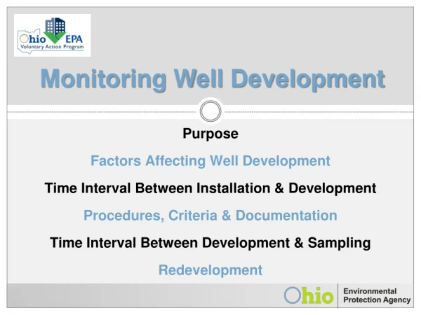
Well Development • After completion, wells are developed to increase specific capacity and improve economic life. • Remove finer materials from the formation. • Pumping • Surging • Compressed air
Pumps Motor • Shallow Wells • Hand-operated • Turbine • Centrifugal (shallow, high volume) • Deep Wells • turbine, submersible Motor turbine submersible
Wellhead Protection • Grout seal, concrete slab, and well seal for sanitary protection.
Well Design, Completion and Development • Well diameter • Dictated by size of pump • Affects cost of the well • Must ensure good hydraulic efficiency • Well depth • Complete to the bottom of the aquifer • More aquifer thickness utilized • Higher specific capacity (Q/s, discharge per unit of drawdown)
Collector Well Sonoma County Water Agency collector well along Russian River near Wholer Bridge. The water agency operates five similar wells on the Russian River. All use the Raney design with laterals extending beneath the river bed in a radial pattern from the main caisson. Each of these wells are capable of producing between 15 and 20 million gallons of water per day. The river water is naturally filtered as it moves through the river bed sediments to the collector wells.
Well Diameter vs Pumping Rate(max 5 ft/sec in casing) Groundwater and Wells, Driscoll, 1986
Drawdown in a Well • Drawdown in a pumped well consists of two components: • Aquifer losses • Head losses that occur in the aquifer where the flow is laminar • Tme-dependent • Vary linearly with the well discharge • Well losses • Aquifer damage during drilling and completion • Turbulent friction losses adjacent to well, in the well and pipe
Well Losses • Excess drawdown due to well design, well construction, or the nature of the aquifer Note UNITS!
Specific Capacity • Specific capacity = Q/sw • Yield per unit of drawdown • gpm/ft, or m3/hr/m • Drawdown in the well • Specific capacity - linear function of Q • Observing change in sw as Q is increased – select optimum pumping rate
Specific Capacity Map http://www.wrd.org/engineering/specific-capacity-well-1.php
Step Drawdown Test • To evaluate well losses • Pump a well at a low rate until drawdown stabilizes • Increase pumping rate • Pump until drawdown stabilizes again • Repeat at least three times
Step Drawdown Test • Plot sw/Q vs Q • Fit straight line • Slope = a1 = C • Intercept = a0 = B
Step-Drawdown Test (Example) C = 1.6x10⁻⁶ day2/m5 = 3.32 min2/m5 Severe deterioration or clogging
Well Efficiency • Specific capacity = Q/s • Relationship between drawdown and discharge of a well • Describes productivity of aquifer and well • Specific capacity decreases with • Time • Increasing Q • Well efficiency = ratio of aquifer loss to total loss
Summary • Well Drilling • Augers • Cable Tool • Rotary • Mud • Well Completion • Unconsolidated formations • Consolidated Formations • Well Screens • Gravel Packs • Well Development • Well Drawdown • Well Losses • Specific Capacity • Step Drawdown Test • Well Efficiency