Download
1 / 19
210 likes | 357 Views
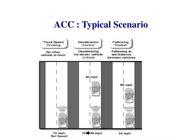
ACC : Typical Scenario. ACC : Proposed Functional Model. Safe Distance minimum allowable distance between host and leading vehicle. measure of system’s response time. Calculating Safe Distance S d = S m + S a Where, S m = minimum separation that should be kept

E N D
ACC : Proposed Functional Model • Safe Distance • minimum allowable distance between host and leading vehicle. • measure of system’s response time. • Calculating Safe Distance Sd = Sm + Sa Where, Sm = minimum separation that should be kept Sa = additional gap for safety
ACC : Proposed Functional Model • Safe distance is calculated for extreme stopping condition • Extreme stopping condition is • Lead vehicle is at maximum deceleration (Amax) • Host is at maximum acceleration (amax)
ACC : Proposed Functional Model Stopping scenario can be represented as - Human interaction time For automatic system delay of sensors Max acceleration a_max Velocity is zero here J_max T+t_1 T+t_1+t_f t_0 T - A_max Max deceleration
ACC : Proposed Functional Model • Sm is a function of Jmax, amax, Amax and T Substituting the values expression for safety distance rule becomes Sd = c1(vi2 – vi-12) + c2vi + c3 for tight vehicle following-vi = vi-1 Sd = c2vi + c3 where, c1, c2 and c3 : functions of Jmax, amax, Amax and T
ACC : Actions ACC can perform following actions - • Accelerate • Decelerate • Decelerate using brakes
ACC : Proposed Algorithm • CVP : Closest Vehicle in Path Assumptions : • Leading vehicle is moving in the same lane • Radar returns speed and distance of CVP • deceleration <= 0.5 : achieved by throttle adjustment • 0.5 <deceleration< max_dec : apply brake force
2nd follower 1st follower lead vehicle Mathematical Model direction of motion Vp V1 • Second order state space model Vk+1a1 a2 Vk b1 Vpk RK+1 - Rmin a3 a4 Rk - Rmin b2 the model reduces to Rk+1 = Rk + Ts. (Vpk - Vk) where, Ts = desired spacing in seconds. . R1 R= dR/dt =Vp-V + =
State Diagram vehicle_sensed() = false vehicle_sensed() = false speed>30 OFF ON /switch on no vehicle ahead /resume /get_val() vehicle_sensd() = true cur_sp = cruise_sp a = 0 cur_sp < cruise_sp vehicle_sensed() = true decelerating with feedback /get_val() accelerating with feedback a < 0 a > 0 cal a vehicle_sensed() = true /get_val() vehicle_sensed() = true /get_val() vehicle ahead max_brk & ACC off ACC off emergency state vehicle_sensed() = false
Ptolemy • Tool used for modeling, simulation, and design of concurrent, real-time systems. • HyVisual - Hybrid System Visual Modeler • a block-diagram editor and simulator for hybrid systems. • supports construction of hierarchical hybrid systems. • It uses a block-diagram representation of ordinary differential equations (ODEs) to define continuous dynamics.
no lead vehicle lead car detected getRadar()getVal() calSafeDist() calAcl() getRadar() getSpeed() State chart ACC off Car_on=true & speed > 35 ACC off = true ACC on controller getRadar() = true & distance < 500m accelerating selAcl() getFeedback() acceleration > 0 getRadar() = true & distance < 500m distance > 500m separation <= safeDist Alarm = false acceleration < 0 unsafe separation decelerating selBreak() selDec() getFeedback() maxBreak() ACCoff = true Alarm = true
Data Storage Architecture for ACC • Requires RTDB for storing • sensor/actuator raw data • sensor/actuator parameters • sensor/actuator base data : derived from raw data using parameter values • derived data (current scenario) : values of safe distance, current speed, acceleration of the host vehicle. • logging data
Data Storage Architecture for ACC (cont.) • Data values are updated periodically. • Validity interval and refresh rate of data items depend upon period of corresponding input task/s. • Non-preemptive tasks : mutual exclusion not required. • Preemptive task : • execution time and period known a priori. • Need of a scheduler which takes care of the mutual exclusion, consistency of data items.
Image & language database user interface communication task data derivation task data processing task sensor reading task Speed sensor decelerate acclero meter accelerate brake actuator input task logging task actuators Database Architecture RTDB raw data Radar sensor dist & speed of leading vehicle parameters (permanent data) speed of host raw sensor data base data safe dist for host (sensor data) decision making task with feedback control derived data (current state) acc of host required acc/dec logging data stable store ROM/EEPROM comm. with cruise control
Transactions • Write only transaction : input from sensors tasks • Read only transaction : input to actuators tasks • Update transaction : tasks reading from/writing to RTDB eg. decision making tasks with feedback control. • Query transaction : communication tasks with user interface & cruise control. • Consistency and concurrency issues
User Display Interface • Displays current scenario : acceleration, speed, warnings etc. • Maps values from RTDB to image and textual information. • Uses image and language database.
Issues in RTDB • maintaining freshness of data items • pull based approach(on demand) • may not be efficient for the transaction with tight deadlines • push based approach • decide upon frequency of updation • depends upon validity interval of data items • Notion of base and derived data items decide upon some threshold value • Use of feedback controller (PID controller)
Some References • Methodology for assessing adaptive cruise control behavior Bareket, Z.; Fancher, P.S.; Huei Peng; Kangwon Lee; Assaf, C.A. Page(s): 123- 131 IEEE Transactions on intelligent transportation systems, Sept 2003. • Dynamic on-demand updating of data in real-time database systems, Thomas Gustafsson Linkng University, Sweden, Proceedings of the 2004 ACM symposium, Page no. 846 - 853, 2004. • Managing Deadline Miss Ratio and Sensor Data Freshness in Real-Time Databases, Kyoung-Don Kang, Sang H. Son, John A. Stankovic, IEEE transaction on knowledge and data engineering, October 2004 (Vol. 16, No. 10) • http://www.cs.virginia.edu/~cl7v/fcs.html • J. A. Stankovic, C. Lu, S. H. Son, and G. Tao, "The Case for Feedback Control Real-Time Scheduling," 11th EuroMicro conference on Real-Time Systems, York, UK, June 1999