Download
1 / 47
490 likes | 699 Views
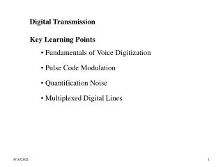
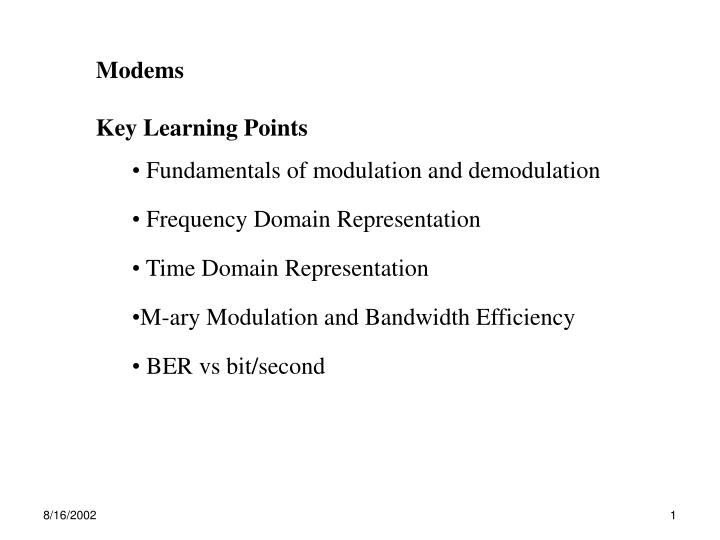
Modems Key Learning Points Fundamentals of modulation and demodulation Frequency Domain Representation Time Domain Representation M-ary Modulation and Bandwidth Efficiency BER vs bit/second. 2.5 Public Carrier Circuits for Limited Geographic Span : use privately owned resources

E N D
Modems • Key Learning Points • Fundamentals of modulation and demodulation • Frequency Domain Representation • Time Domain Representation • M-ary Modulation and Bandwidth Efficiency • BER vs bit/second
2.5 Public Carrier Circuits • for Limited Geographic Span: use privately owned resources • e.g. Local Area Network, Routers, Hubs • for Larger Geographic Span: • Line of Sight (LOS) uwave • satellite links • public carriers (e.g. Sprint, MCI, …) • - analog PSTN using modems • - digital leased lines: T1, T3, ISDN
2.5.1: Analog PSTN Circuit • designed for analog voice transmission (mixed audio • frequencies ) • Bandwidth ranges 400-3000Hz • - DC power supply will not pass low frequency signals • (1111… or 0000…) • - 2 voltage levels for different signals won’t work • (0 output for 1111… or 0000…)
Binary Data Transmission over PSTN Requires Modem • Modulator: Convert binary data into from compatible with • PSTN at transmitter • Demodulator: Convert signal back, recover data at receiver • 2 options for conventional PSTN modem connection: • 1. short-term switched path: dialing & setting up ~ • phone call • 2. leased line: bypass normal switching equipment • (switch exchanges) • - set-up on long-term basis • - economical only if utilization is high • - operating characteristics accurately quantified • higher signal rates
Modulation: three general types which can be combined • (i) Amplitude Shift Key, • (ii) Frequency Shift Key, • (iii) Phase Shift Key • binary data requires at least 2 signal levels • as binary datakeys between 1 and 0 • signal shifts between 2 levels • different methods require different amounts of BW
(1)carrier signal: vc(t) = cos wct(assume unity amplitude) • carrier frequency, fc: (Hz) or wc= 2fc(rads) • fc selected within PSTN Bandwidth (1000Hz-2000Hz) • (2) binary data signal,vd(t) • fundamental frequency of data signal: w0= 2f0 mathematically modulation is vc(t)vd(t)
unipolar periodic data signal given by: vd(t)= modulated signal given by vASK(t) = vc(t) vd(t) • 1. Amplitude Shift Key (ASK) Principal of Operation: • - amplitude of audio tone (fc) switched between 2 levels • - bit rate of transmitted binary signal determines switching rate & • bandwidth • - binary data is effectively carried by carrier signal
= = *2cosA cosB = cos(A-B) + cos(A+B) vASK(t) = vc(t) vd(t)
vASK(t) = • vASK(t)consists of original data signalvd(t) • translated in frequency by wc(wc±w0, wc ±3w0, wc ± 5w0) … • DC component translated to sinusoidal component at wc • 2 frequency components for fundamental & each harmonic • - frequency components are equally space on either side of fc • - spectral components are known as sidebands • -each bandpass component at ½ power of original baseband • sidebands
+V 0 digital signal carrier signal 1 0 1 0 1 0 ASK – time domain 6f0 2f0 signal power ASK – frequency domain fc–3f0fc–f0fc fc+f0 fc+3f0 f
Recall from discussion of Limited Bandwidth: • higher channel bandwidth received signal is closer to • transmitted • given data rate = R, minimum channel bandwidth for satisfactory • performance in the worst case • - f0of “101010…” (shortest period highest f0) • - f0 = ½ R
minimum channel bandwidth for ASK • - to receive only f0bandwidth, B = 2f0= R • - to receive f0 and 3rd Harmonic bandwitdh = 6f0= 3R, • component at carrier frequency is present in received signal, • contains no information (inefficient) • - Nyquist: maximum achievable data rate for ideal channel • C = 2B • Alternatively, let B = 2f0 max data rate R = B =22f0 • both primary sidebands used to compute minimum BW • either contains required signal, f0
SSB-ASK passband power filter filter fc–5f0 … fc–f0fc fc+f0 …. fc+5f0 f • Single Side Band (SSB) • use band pass filter on transmitter lower required bandwidth to • B =f0 (Nyquist rate) • - limit pass band • - remove lower sidebands: (fc - f0) • e.g. limit pass band to fc + (fc + 5f0) • primary sideband signal power cut in ½ relative to vc (t ) • - reduces Signal to Noise Ration increases BER
Demodulation: Recover transmitted Signal – at receiver • assume ideal channel - no noise, distortion, attenuation • practically, problem is more difficult receiver multipliesvASK(t) by vc (t) vd(t)v2c(t) received signal = vASK(t) vASK(t) =
collecting terms yields: • Produces 2 versions of received signal • each at ½ original power • both with data contained in sidebands • one is centered at 2fc(high frequency component ) • other is at baseband (fc - fc) = 0
filter all components < 3f0 Recovered Signal = hi frequency components completely filtered • Select baseband signal with Low Pass filter: • Low pass filter output = bandwidth limited version of vd(t) • pass only 0, f03f0, (assume 3rd harmonic used )
Original Data Signal vASK(t) = Modulated Signal Demodulated Signal vd(t)= Recovered Signal after low pass filtering, fcutoff = 3fn
vd(t) f0 3f0 f vASK(t) fc–3f0 fc–f0 fc fc+f0 fc+3f0f demodulated f0 3f0 2 fc–3f0 2fc–f0 2fc 2fc+f0 2fc+3f0 filtered and recovered f0 3f0 Ideal ASK Modulation – Frequency Domain
vASK (t) vd‘(t) vd(t) PSTN cos(wct) cos(w’ct) Fantasy: Received Signal = ½ power of Transmitted Signal • More Practically • if attenuation is included 10-30dB attenuation common • if noise is included received power > noise floor (SNR) • if distortion is included must use equalizers, match filter, etc • if carriers aren’t synchronized phase noise wc(t)-w’c(t) = (t) • receiver must synchronize sampling interval to recover signal
ASK is simple to implement, not used in early, low rate modems • - PSTN long haul switching & transmission systems were analog • - voice & data signals transmitted & switched as analog signals • - ASK sensitive to resulting variable signal attenuation • More recently PSTN long haul switching & transmission systems are digital • - source signal is analog only to local exchange • - converted digital signal retains form thru-out network • - significant improvement in electrical characteristics of PSTN • ckts • ASK & PSK used to in higher rate modems
bandpass data-rate 300bps 1200bps 4800bps Required BW 2 f0 300Hz 1200Hz 4800Hz 6f0 900Hz 3600Hz 14400Hz ie: Estimate BW to transmit f0 & 3f0using ASK for data rates: (without SSB) baseband
vFSK(t) = vc1(t) vd(t) + vc2(t) vd’(t) = cos(wc1t) vd(t) + cos(wc2t) vd’(t) • 2. Frequency Shift Key (FSK):used in early low rate modems • Principal of Operation • use 2 fixed amplitude carrier signals, vc1 (t), vc2 (t)to avoid reliance • on amplitude variance • 2 carrier frequencies fc1 , fc2 frequency shift:fs = fc2 - fc1 • modulation is equivalent to summing 2 ASK modulators • - one carrier uses original data signal,vd(t) • - other carrier uses compliment of data signal, v’d(t) • - 2 data signals: vd(t) and vd’(t) = 1- vd(t)
1 0 1 0 1 0 data vd(t) carrier vc1(t) +V -V 0 1 0 1 0 1 +V -V inverted data v’d(t) carrier vc2(t)
FSK – time domain vFSK(t)=cos wc1t + cos wc2t
FSK – frequency domain 6f01 2f01 6f02 2f02 vFSK(t) signal power fc1–3f01fc1–f01 fc1 fc1+f01fc1+3f01 fc2–3f02 fc2–f02 fc2 fc2+f02 fc2+3f02 frequency shift: fs = fc2 – fc1
FSK bandwidth requirements • fc1 modulates ‘1’ and fc2modulates ‘0’ • - minimum bandwidth for each carrier is ½ R • - highest fundamental freq component of each carrier ½ of ASK • assume justf0component received(no harmonics) • - let fs= fc2-fc1 total bandwidth for FSK is2f0-FSK + fs • - since f0-FSK ½ f0-ASK total BW f0-ASK + fs • - with 3rd harmonic: 6f0 ASK+ fs
choice of fsis significant - naïve choice vs efficient choice Attn (dB) 0 -10 -20 -30 -40 • spectrum of simple FSK vs CPFSK techniques • - Sunde FSK • - MSK Sunde FSK MSK fc1 fc2 -3 -2 -1 0 1 2 3 frequency = 1/Tb
input data phase jumps cos w1t VCO switch cos w2t continuous phase FSK (CPFSK) with VCO based oscillator input data cos wct Implementation of FSK simple FSK system with phase jumps
modem modem modulator ‘0’ = 1070 Hz ‘1’ = 1270 Hz demodulator ‘0’ = 1070 Hz ‘1’ = 1270 Hz DTE DTE demodulator ’0’ = 2025 Hz ‘1’= 2225 Hz modulator ’0’ = 2025 Hz ’1’ = 2225 Hz • ie: EIA for Bell 103, ITU-T for V.21 - FSK modems, full-duplex links • f0 = 75 Hz R = 150 bps • 2f0 = 150 Hz R = 300 bps • fs = 200Hz, separation between primary sidebands = 50Hz • space = binary 0, • mark = binary 1
phase coherent ‘1’ ‘0’ • 3.PSK:phase shifts in carrier encode bits in data stream • carrier frequency & amplitude are constant (constant envelope) • i. phase coherent PSK: 2 fixed carriers 180° phase shift • represents ‘1’ or ‘0’ • One signal is simply inverse of other • Disadvantage: requires reference carrier signal at receiver • - received phase signal is compared to local reference carrier • - more complex demodulation circuitry
90° phase shift relative to current signal next bit = ‘0’ 270° phase shift relative to current signal next bit = ‘1’ differential 90° = ‘0’ 270° = ‘1’’ • ii. differential PSK: phase shift at each bit transition • irrespective of whether ‘111…’ or ‘000…’ transmitted • demodulation: determine magnitude of each phase shift (not • absolute value)
vc(t) = cos wct vd(t) = vPSK(t) = vd(t)vc(t) vPSK(t) = ì ü 2 1 1 = ± - ± - ± + cos( w w ) t cos( w 3 w ) t cos( w 5 w ) t ... í ý c 0 c 0 c 0 p 3 5 î þ • PSK Bandwidth requirement: represent data in bi-polar form • negative signal level results in 180° phase change in carrier • • assume unity amplitude, fundamental freq = w0
signal power fc–3f0 fc–f0 fc fc+f0 fc+3f0f 6f0 2f0
PSK BW Requirements • - same bandwidth as ASK, no carrier component, coswct at wc • - assume 10101… w/ only f0to be received min BW = 2 f0 • absence of carrier component meansmore power to sidebands • sidebands contain data more resilient to noise than FSK, ASK • with band pass filter on transmitter band limit transmitted signal to fc • achieve nyquist rate for minimum bandwidth required ½ R = f0 • (~ ASK) • no component at wc all received power in data carrying • signal,fc ± f0, …
Q (quadrature) 180 = 0 0 =1 I (in-phase) • Phase Diagram • 2 axis: in-phase, I & quadrature, Q • represents carrier as vector, length = amplitude • vector rotates CCW around axis angular frequency, w • - ‘1’ represented as vector in phase with carrier • - ‘0’ represented as vector 180° out of phase with carrier
4. Multilevel Modulation • Advanced modulation techniques higher bit rates • - multi-level signaling • - mix of basic schemes (PSK, ASK) • - more complex (cost), higher bit error rate • Used in all digital PSTN (switching & transmission) • Multi-Level Signal(use amplitude, phase, or frequency) • use n signal levels each signal represents log2n data bits • - 4 signal levels 2 bits/signal element • - 8 signal levels 3 bits/signal element • - 16 signal levels 4 bits/signal element
Q (quadrature) 90o = 00 270o = 10 180o= 00 0o = 11I (in-phase) • QPSK (4-PSK): • 4 signals (0°, 90°, 180°, 270°) 2 bits/signal
QAM – (quad amplitude modulation) Combine ASK & PSK • QAM-16 levels per signal element 4-bits per symbol • - 12 phase levels • - 4 amplitudes levels • - different amplitude associated with adjacent phases • - 48 total signal levels possible bits/symbol = 5 2(t) 1(t)
using 16 of 48 possible signals makes recovery less prone to errors • - same amplitude levels have large phase variation • - same phase angles have large amplitude variation • - extra bit can be used for forward error correction • practical limits to M-level signalling: • more phase/amplitude levels difference between unique signal • symbols is reduced • increases impact of channel impairments (noise distortion, • attenuation • scheme’s robustness depends on proximity of adjacent points in • constellation • complexity rises cost, risk, rate of failures rise
Q (quadrature) 90o = 001 135o = 111 45o = 011 8 signals 3 bits/signal I (in-phase) 0o = 010 180o= 100 300o= 110 225o =101 270o = 111 received signal region bit error likely received signal region bit error unlikely • reduce error rate: • maximize distance between adjacent points • grey coding – adjacent symbols differ by 1 bit • offset phase angles for adjacent amplitude
All modulation schemes scramble & descramble • reduces probability that consecutive bits in sequence are in • adjacent bit positions • - at transmitter: bit stream scrambled using pseudo random • sequence • - at receiver: bit stream descrambled restore bit stream • - used in V.29 modems (fax machines @ 9600 bps)
trellis–code modulation (TCM) - another redundancy scheme • - use all 32 amplitude –phase alternatives • - resulting5 bit symbols contain only 4 data bits • - 5th bit generated using convolutional encoder, used for error • correction • at transmitter: each 4-bit set in source stream converted to 5 bits • at receiver: most likely 4 data bits determined • - with no bit errors correct 4 bit set collected • - with bit errors some probability that correct 4 bits selected used in V.32 for rates up to 14.4kbps V.34 fast modems rates up to 19.2k, 24k, & 28k
2.5.1a. Cable Modems (CM) • Connection speed 3-50 Mbit/s • Distance can be 100 km or more • Master-Slave Topology (CATV is traditionally simplex) • CATV networks are Hybrid Fibre-Coax (HFC) networks • - fiber-optic cables from the Head-End to locations near the • subscriber • - the signal is converted to coaxial cables to subscriber premises. • CMTS:Cable Modem Termination System • - connects cable TV network to data network • - CMTS can drive 1-2000 simultaneous CMs on 1 TV • channel
CMTS (head) Upstream Demodulator QPSK/16-QAM carrier freq. 5-65MHz BW: 2MHz Data Rate: 3Mbps Cable Modem 1 Upstream Modulator QPSK/16-QAM carrier freq: 5-65ZMHz BW: 2MHz Data Rate: 3Mbps Cable Modem 4 Cable Modem 3 Cable Modem 2 Downstream Modulator 64 QAM/256QAM carrier freq: 65-850MHz BW: 6-8MHz Data Rate: 27-56Mbps Downstream Demodulator 64 QAM/256QAM carrier freq: 65-850MHz BW: 6-8MHz Data Rate: 27-56Mbps
2.5.1.b Digital Subscriber Line (DSL) – up to 52Mbps over traditional phone lines • uses carrier frequencies between 25KHz .. 1MHz • always on – no need to dial Internet Service Provider (ISP) • dedicated connections (not shared with your neighbors) • voice & data over a single line • more expensive, additional hardware required • special DSL modem at your computer • DSL Multiplexer (DSLAM) at central office • - separates voice/data streams • - sends voice stream to phone company & data stream to ISP • limited availability • connection speed is dependent on distance from phone company • data rate is lowered to reduce distortion • DSL link must be within 2 miles of central office