Download
1 / 24
240 likes | 255 Views
Interfacing--MEMS; energy domains; mechanical and fluidic devices. MEMS (Microelectromechanical systems) (Other commonly used terms: Microsystems (Europe); Microfluidics; Mechatronics (Japan) )

E N D
Interfacing--MEMS; energy domains; mechanical and fluidic devices Silicon Programming--Introduction to MEMS
MEMS (Microelectromechanical systems) (Other commonly used terms: Microsystems (Europe); Microfluidics; Mechatronics (Japan) ) All these terms refer to "systems" incorporating electrical elements and elements from other domains into a "chip" or "integrated circuit". Both miniaturization and integration are usually implied. Another term commonly used is "SOC", which stands for "system on a chip". Silicon Programming--Introduction to MEMS
Motivations for MEMS: -----space (area) savings -----power reduction (can we use batteries?) -----portability (reduced weight / power) -----reliability--because of integration -----economic savings--"mass produce" elements as VLSI chips are currently produced -----application of well-understood VLSI processing techniques to other domains Silicon Programming--Introduction to MEMS
Application areas (a sampling)-- -----automotive systems -----environmental control / monitoring -----health care -----defense systems ----- automated manufacturing Example applications (see, e.g., Analog Devices website, www.analog.com):: --airbags: change in acceleration (force) is translated into signal to deploy airbag --navigation and stabilization: micro gyroscopes provide a frame of reference in navigation and stabilization systems in cars, planes, etc. --”lab on a chip”: biological / chemical procedures can be carried out on one integrated chip (Lab on a Chip journal: http://www.rsc.org/is/journals/current/loc/locpub.htm) Silicon Programming--Introduction to MEMS
Area is INHERENTLY MULTIDISCIPLINARY (based on today's "disciplines") How old is this area? (~ 30 years) basic reference: K. Petersen, Silicon as a mechanical material, IEEE Proceedings 70 (5), May 1982, 420-457. Silicon Programming--Introduction to MEMS
Basic idea: IC's perform (electronic) calculations extremely well; I/O is NOT generally in the electrical domain--how can I/O elements (“sensors” and “actuators”, or "transducers")be integrated? Silicon Programming--Introduction to MEMS
Energy Domains: 1. thermal--temperature, heat, heat flow, etc. 2. mechanical--force, pressure, ve;ocity, acceleration, position, etc. 3. chemical--concentration, material composition, reaction rate, etc. 4. magnetic--magnetic field intensity, flux density, magnetization, etc. 5. radiant--intensity, wavelength, polarizaion, phase, etc. 6. electrical--voltage, current, charge, etc. Silicon Programming--Introduction to MEMS
Relation to IC's: Typical IC is built up of "layers" of material. These layers can be used to make other devices, e.g., cantilever beams for sensing and actuating Techniques for "machining" are those used in IC fabrication--how can they be used / modified to make devices usable in other domains? Silicon Programming--Introduction to MEMS
Devices are generally divided into two classes according to processing required: a. "surface micromachining" (2.5D devices) uses “layers” b. "bulk micromachining" (true 3D devices) Silicon Programming--Introduction to MEMS
examples: beams cantilever beams membranes ducts motors, movable parts http://www.sfu.ca/immr/projects/ensc494-01/acoppin/designs.html Silicon Programming--Introduction to MEMS
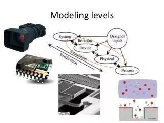
How can MEMS development make use of well-understood IC CAD capabilities? What extensions are needed for CAD for MEMS? Recall: 1. Predicting IC performance requires input from fabrication, design, and environment. 2. Tools for incorporating information from each of these domains are necessary for "rapid prototyping" which make many IC designs economically feasible. Silicon Programming--Introduction to MEMS
Comparisons of Mechanical Properties (Petersen) Property Si SiO2 Steel Al Yield (1010 dyne/cm2) 7.0 8.4 4.2 0.17 Hardness (kg/mm2) 850 820 1500 130 Young's mod (1012dyne/cm2) 1.9 0.73 4.9 0.7 Density (gr/cm3) 2.3 2.5 7.9 2.7 Therm. cond (W/cmoC) 1.57 .014 0.97 2.36 Thermal exp (10-6/oC) 2.33 0.55 12 25 Silicon Programming--Introduction to MEMS
Tasks: Specify-Design-Simulate-Fab-Test-Maintain ===================================================================================== LEVELS|| VIEWS || Behavioral Structural Physical ===================================================================================== 4 || Specifications, CPUs,Memory, Partitions || Systems Switches, Complex || MEMS ------------------------------------------------------------------------------------------------------------------------------------------------ 3 || Algorithms Data Structures Clusters ------------------------------------------------------------------------------------------------------------------------------------------------ 2 || Register Transfers ALUs, Registers, Floorplans || Electromechanical || Components ----------------------------------------------------------------------------------------------------------------------------------------------- 1 || Boolean Equations, Gates, Flip-flops, Cells, || FSMs, MechanicalSensors, Actuators Modules || Behavior ----------------------------------------------------------------------------------------------------------------------------------------------- 0 || Transfer Functions Transistors, Wires, Layout || Contacts, Vias, Geometry || Beams, Membranes, || Holes, Grooves, || Joints ==================================================================================== Silicon Programming--Introduction to MEMS
Cantilever beam--static and dynamic behavior; extending VHDL to other domains (VHDL-AMS) Silicon Programming--Introduction to MEMS
We will look at how a cantilever beam is built in a “typical” MEMS process--the “MUMPS” process (MultiUser MEMS Process) there are two structural (polysilicon) layers. Structures can be made of: first poly by itself, second poly by itself, first poly-second poly together. typical layer thickness: ~ 2 microns--"large" (compared to today's circuit elements) Silicon Programming--Introduction to MEMS
Simple cantilever beam, height h, length l, width w, thickness t. If the beam is made of a material with density p and Young’s modulus E, then mass m and moment of inertia I are given by: m = pwtl I = (wt3) / 12 If u = distance from the beam's anchor to its end, 0 <= u <= l, and force F(u) is applied at point u, the beam will be displaced a distance x(u). What is x(u)? Silicon Programming--Introduction to MEMS
If a constant force F is applied to the free end of the beam, then its maximum (static) deflection is given by standard equation for a maximum deflection of a cantilever beam of constant cross section : where D is the deflection of the free end of the beam, F is the force applied to the free end, L is the length of the beam, and EI is the flexural rigidity of the beam (E = Young's modulus). Silicon Programming--Introduction to MEMS
If F varies with respect to time s, then we actually have F = F( s,u) and we seek the dynamic solution x = x(s,u). Silicon Programming--Introduction to MEMS
Method 1. The cantilever beam as a spring. AssumeF is a function of time s alone, applied at the free end of the beam. F = m x ' ' + B x ' + kx, where the spring constant k is given by k = (3EI) / (L3) and the damping coefficient B is given (experimentally) by B = 2*((mk)1/2) / 5. Silicon Programming--Introduction to MEMS
F = m x ' ' + B x ' + kx can be translated into the electrical domain: I = C V ' + (1/R) V + (1/L)V(y)dy where I = current, C = capacitance, R = resistance, L = inductance, V = voltage. (This represents a circuit with R,C,L in parallel). So if we use this form of the equation we can simulate the behavior of the beam using SPICE. Silicon Programming--Introduction to MEMS
Method 2. Finite element analysis. This is a standard method for dealing numerically with complex systems. Here we can break the beam into sections and model the behavior of each section, keeping them "tied" together at the ends. This allows us to deal with a force which varies along the beam length. Silicon Programming--Introduction to MEMS
A beam-capacitor system. By adding an insulated plate on the base for the beam, we can create a capacitor. Here the distance (h - x in the equation above, if we ignore the plate height) is the distance between the two capacitor plates. The equation for the attractive force at the end of the beam is: F = (AE0V2) / (2y2), where A is the area of the capacitor plate, V is the voltage, E0 is the permittivity of air (=8.85 x 10⁻¹²), and y is the distance between the two plates. Silicon Programming--Introduction to MEMS
example: VHDL-AMS (VHDL with Analog and Mixed Signal extensions) model of cantilever beam: entity cantbeam is end entity cantbeam; architecture simple of cantbeam is quantity x: real; quantity v: real; quantity a: real; quantity F: real; constant L: real := 20.0E-6; constant W: real := 10.0E-6; constant H: real := 1.5E-6; constant P: real := 2.26E3; constant M: real := L*W*H*P; constant Y: real := 170.0E9; constant IZ: real:= (W*H*H*H)/12.0; constant Rigidity: real := Y*IZ; constant k: real := (3.0*Rigidity)/(L*L*L); constant B: real := 0.4*sqrt(M*K); begin. b1: break v => 0.0, a => 0.0, x => 0.0, F => 0.0; force: F == F1 + F2 + F3; force1: F1 == M*a; force2: F2 == k*x; force3: F3 == B*v; vel: v == x'dot; accel: a == v'dot; end architecture simple; Declarations Equations Silicon Programming--Introduction to MEMS
Initialize: Process (Vin,Length,Width) • VARIABLE MASS,MOMENT,RIG,SpringK: real; • BEGIN • Volt := Vin; • L := Length; • W := Width; • MASS := L*W*H*P; • M := MASS; • MOMENT := (W*H*H*H)/12.0; • IZ := MOMENT; • RIG := Y*IZ; • Rigidity := RIG; • B := 0.4*sqrt(M*K); • SpringK := (3.0*Rigidity)/(L*L*L); • k := SpringK; • END process; • Calc_Force: Process • VARIABLE Area, Perm,AttractForce: real; • BEGIN • Area := L*W; • Perm := Eo; • AttractForce:= (Area*Perm*Volt*Volt)/(2.0*x*x); • F := AttractForce; • END process; • Force_applied: F == F1 + F2 + F3; • force1: F1 == M*a; • force2: F2 == k*x; • force3: F3 == B*v; • vel: v == x'dot; • accel: a == v'dot; • deflection = x; • Force = F; • end architecture simple; • b1: break Volt => 0.0, a => 0.0, x => 0.0, F => 0.0; • InputTestBench: Process • File Infile : text OPEN READ_MODE IS "cantbeam.in"; • VARIABLE linebuf : line; • VARIABLE vtemp,ltemp,wtemp,htemp :real; • BEGINWHILE (NOT (endfile(Infile))) LOOPreadline(Infile,linebuf); • read(linebuf,vtemp); • Vin <= vtemp; read(linebuf,ltemp); • Length <= ltemp; read(linebuf,wtemp); • Width <= wtemp; • WAIT FOR 100 ns; • END LOOP; • END process; Cantilever beam actuator: entity cantbeamactuator is port(Vin,Length,Width: in real; deflection,Force: out real); end entity cantbeamactuator; architecture simple of cantbeamactuator is quantity x: real; quantity Volt: real; quantity v: real; quantity a: real; quantity F: real; quantity L: real; quantity W: real; quantity H: real; quantity M: real; quantity IZ: real; quantity Rigidity: real; quantity k: real; constant P: real := 2.26E3; constant Y: real := 170.0E9; constant Eo: real:= 8.85E-12; constant H: real := 1.5E-6; begin Silicon Programming--Introduction to MEMS