Download
1 / 17
180 likes | 424 Views
Nanosatellite Communication And MEMS Technology. Overview. Changing satellite architecture Smaller, distributed systems Require RF communication MEMS communication devices Switches Antennas Signal Filters Phase Shifters Completed picosatellite experiment Suggestions for future.

E N D
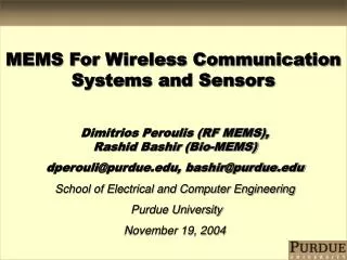
Nanosatellite Communication And MEMS Technology
Overview • Changing satellite architecture • Smaller, distributed systems • Require RF communication • MEMS communication devices • Switches • Antennas • Signal Filters • Phase Shifters • Completed picosatellite experiment • Suggestions for future
NASA Administrator Daniel Goldin sought new methods for space exploration Reduced mass results in significant gain in shrinking launching cost Less expensive to launch small components individually rather than monolithic device Low Earth Orbit (LEO) ~ $10k per kilogram Geosynchronous Orbit (GEO) ~ $50k per kilogram Situation perfectly suited for MEMS devices Low mass, resistant to inertial and vibration damage Endurance in high radiation environments Faster, Better, Cheaper
Distributed Satellite Architecture • Spread component capabilities to separate vehicles • Individualized vehicles faster to produce because of less system integration • Easily replaceable for component failure • Eliminate physical hardware connections and reduce overall mass
Capabilities of DSA • Increase aperture size for interferometer and distributed radar systems • Hubble, Chandra limited size due to launch constraints • Failures aboard Hubble are repairable by humans; Chandra out of reach Hubble Space Telescope
Planned DSA Missions TechSat 21 Distributed Radar (AFRL) Terrestrial Planet Finder (JPL) Space Technology 5 & 6 (NASA - NMP) – First to use primarily MEMS components
Consideration for DSA • Actively control relative positions and velocities • Robust, reliable feedback from sensors possibly onboard separate vehicle • Remote RF communication necessary • RF comm. requires sender/receiver pair with signal processing hardware • MEMS RF devices explored: • Switches • Antennas • Signal Filters • Phase Shifters
DC-Contact Coplanar Waveguide Shunt Switch • Switches used for beam shaping and steering • RF MEMS switches have better efficiency and lower insertion losses than conventional switches • Ideal for space: • Rapid response • Good power handling • Wide bandwidth • Good EM isolation • High open isolation • May experience stiction and slow response time
DC-Contact Coplanar Waveguide Shunt Switch • Force balance can be used to calculate the electrostatic force • The restoring force is found from spring equation • For deflections greater than 1/3 d, pull in occurs • Pull-in voltage not affected by dielectric layer • A, e0, V, d, x, and k are the projected area of the electrodes, permittivity of the free space, applied voltage, gap between the line and bridge, deflection of the bridge, and spring constant respectively
DC-Contact Coplanar Waveguide Shunt Switch • Model of RsL circuit in isolation • Rc, Rl are contact resistance and contact line resistance • Model of R-C circuit, insertion • Capacitors model coupling between switch and pull-in electrodes
DC-Contact Coplanar Waveguide Shunt Switch • Process similar to other MEMS devices manufactured by batch lithographic processing • 1.7 mm PECVD SiO2 grown as sacrificial layer; dimples created by partially etching 5500 Å; 0.8 mm sputtered Au creates bridge; buffered HF solution used to remove SiO2 • RSC microrelay: micromachine @ 250 C; SiO2 removed by dry release etching in oxygen plasma
All RF communication circuits require at least one filter to pull out a desired signal or insert one to be transmitted Currently done with solid state electronics Surface Acoustic Wave (SAW) filters or back-end digital signal processing MEMS offers passive front-end signal processing capability Compact one-chip design High fidelity signal handling Tunable configuration Filter sensitivity and quality factor (Q) would be greatly increased Different MEMS filter designs are possible Coplanar waveguide (CPW) layout on thin GaAs membrane Flexural beam resonator CPW filter structure Signal Filters CPW Filter Beam Resonator
Improved performance of components achieved by integrating antenna design with other components on same chip “Smart” antennas Double-folded shot antenna 2.5 mm gold deposited on silicon oxide dielectric membrane Cross members placed half wavelength apart for optimal performance Reconfigurable V-Antenna Arms of antenna can be moved independently with comb-drive actuators Structure fabricated using silicon multi-layer surface micromachining When both arms moved at fixed angle, antenna can steer beam to focus reception or transmission Adjusting relative angle of arms can modify shape of beam Antennas 77 GHz Double-Folded Slot Antenna 17.5 GHz V-Antenna
Phased-array antenna Able to transmit or receive signals from different directions without being physically re-oriented Currently this is done with FET or diode technology Low power consumption but high signal loss MEMS design would cut down on signal loss, especially at frequency range 8-120 GHz Not as many amplifiers are needed to boost signal, resulting in power savings Straightforward design: MEMS switches used in place of solid-state components Large body of research already exists in phase shifter design and application Proper placement of switches is known Significant cost benefits MEMS-based array could cut cost of complex phase-shifter by an order of magnitude Phase Shifters Phase shifter composed of array of RF-MEMS switches
Picosatellite Mission • Satellite mission has been completed proving feasibility of MEMS devices in space • RF-MEMS switches in picosatellite (< 1 kg) • Stanford-designed Orbiting Picosatellite Automated Launcher (OPAL) launched in 2000 released testing platform • Two tethered picosatellites in LEO containing four RF-MEMS switches in series • Switches developed by Rockwell Science Center (RSC) • Each satellite measures 3 x 4 x 1 in3 and weighs less than half a pound • Actual communication system made with standard radio components • MEMS switches used only for experiment
Figure 15. Picosatellite system architecture [21] Switch Experiment • RF switches cycled through on and off states at 500 Hz • During contact time with ground station, test data and statistics downloaded • Relatively inexpensive test was successful • Unfortunately, due to difficulties establishing initial contact with the picosatellites, mission was prematurely ended when power ran out • If communication system had been composed of MEMS devices, mission could have been lengthened! • Future missions are planned: AFRL MightySat 2.1 and beyond
Conclusions • Network of MEMS satellites for continual base station communication • Tap into network much like Internet • Eliminates remote control stations • MEMS are ideal for reducing cost of space exploration • Reduced overall mass (cheaper launch) • Increased efficiency • Adaptability • Robust to space environment • Faster, Better, Cheaper… and Smaller