Download
1 / 1
10 likes | 151 Views
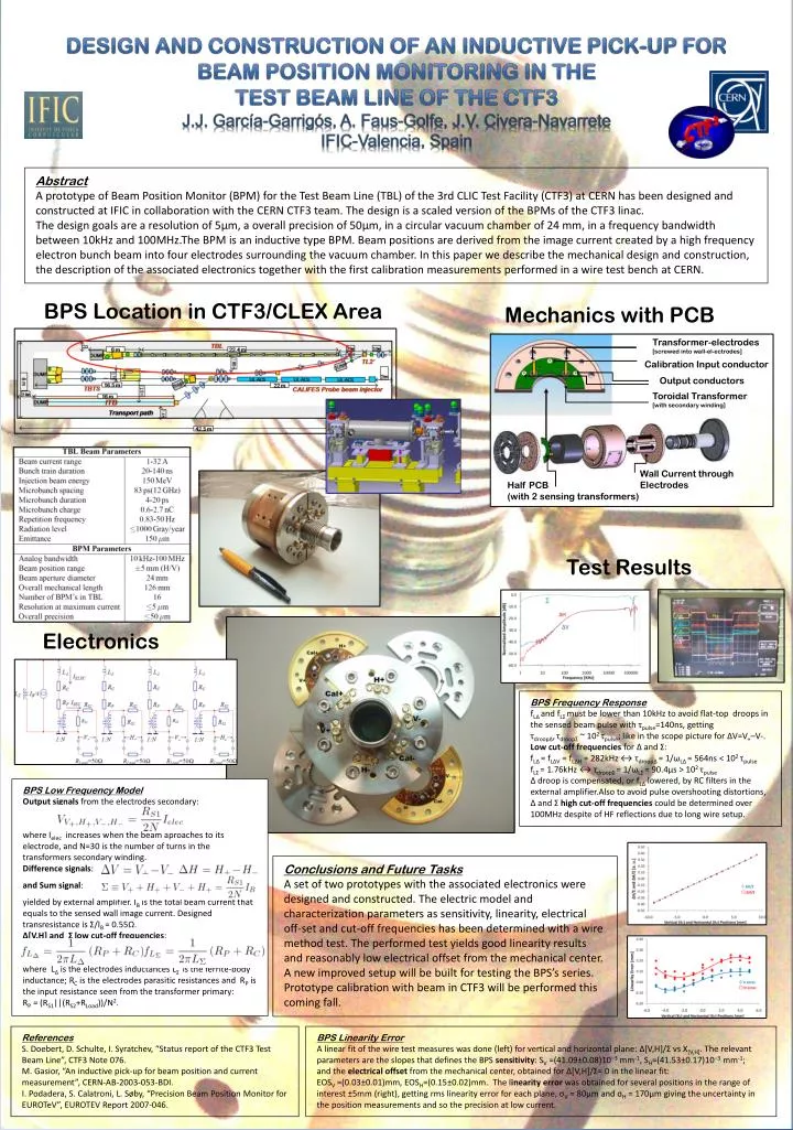
DESIGN AND CONSTRUCTION OF AN INDUCTIVE PICK-UP FOR BEAM POSITION MONITORING IN THE TEST BEAM LINE OF THE CTF3 J.J. García-Garrigós, A. Faus-Golfe, J.V. Civera-Navarrete IFIC-Valencia, Spain. Abstract

E N D
DESIGN AND CONSTRUCTION OF AN INDUCTIVE PICK-UP FOR BEAM POSITION MONITORING IN THE TEST BEAM LINE OF THE CTF3 J.J. García-Garrigós, A. Faus-Golfe, J.V. Civera-Navarrete IFIC-Valencia, Spain Abstract A prototype of Beam Position Monitor (BPM) for the Test Beam Line (TBL) of the 3rd CLIC Test Facility (CTF3) at CERN has been designed and constructed at IFIC in collaboration with the CERN CTF3 team. The design is a scaled version of the BPMs of the CTF3 linac. The design goals are a resolution of 5μm, a overall precision of 50μm, in a circular vacuum chamber of 24 mm, in a frequency bandwidth between 10kHz and 100MHz.The BPM is an inductive type BPM. Beam positions are derived from the image current created by a high frequency electron bunch beam into four electrodes surrounding the vacuum chamber. In this paper we describe the mechanical design and construction, the description of the associated electronics together with the first calibration measurements performed in a wire test bench at CERN. BPS Location in CTF3/CLEX Area Mechanics with PCB Transformer-electrodes [screwed into wall-el-ectrodes] Calibration Input conductor Output conductors Toroidal Transformer [with secondary winding] Wall Current through Electrodes Half PCB (with 2 sensing transformers) Test Results Electronics BPS Frequency Response fLΔand fLΣ must be lower than 10kHz to avoid flat-top droops in the sensed beam pulse with τpulse=140ns, getting τdroopΔ,τdroopΣ ~ 102τpulse; like in the scope picture for ΔV=V+–V-. Low cut-off frequencies for Δ and Σ: fLΔ= fLΔV = fLΔH = 282kHz ↔ τdroopΔ= 1/ωLΔ= 564ns < 102τpulse fLΣ= 1.76kHz ↔ τdroopΣ= 1/ωLΣ= 90.4μs > 102τpulse Δ droop is compensated, or fLΔ lowered, by RC filters in the external amplifier.Also to avoid pulse overshooting distortions, Δ and Σ high cut-off frequencies could be determined over 100MHz despite of HF reflections due to long wire setup. BPS Low Frequency Model Output signals from the electrodes secondary: where Ielec increases when the beam aproaches to its electrode, and N=30 is the number of turns in the transformers secondary winding. Difference signals: and Sum signal: yielded by external amplifier. IB is the total beam current that equals to the sensed wall image current. Designed transresistance is Σ/IB = 0.55Ω. Δ[V,H] and Σlow cut-off frequencies: where LΔ is the electrodes inductances LΣ is the ferrite-body inductance; RC is the electrodes parasitic resistances and RP is the input resistance seen from the transformer primary: RP = (RS1||(RS2+RLoad))/N2. Conclusions and Future Tasks A set of two prototypes with the associated electronics were designed and constructed. The electric model and characterization parameters as sensitivity, linearity, electrical off-set and cut-off frequencies has been determined with a wire method test. The performed test yields good linearity results and reasonably low electrical offset from the mechanical center. A new improved setup will be built for testing the BPS’s series. Prototype calibration with beam in CTF3 will be performed this coming fall. References S. Doebert, D. Schulte, I. Syratchev, “Status report of the CTF3 Test Beam Line”, CTF3 Note 076. M. Gasior, “An inductive pick-up for beam position and current measurement”, CERN-AB-2003-053-BDI. I. Podadera, S. Calatroni, L. Søby, “Precision Beam Position Monitor for EUROTeV”, EUROTEV Report 2007-046. BPS Linearity Error A linear fit of the wire test measures was done (left) for vertical and horizontal plane: Δ[V,H]/Σ vs X[V,H]. The relevant parameters are the slopes that defines the BPS sensitivity: SV =(41.09±0.08)10−3 mm-1, SH=(41.53±0.17)10−3 mm-1; and the electrical offset from the mechanical center, obtained for Δ[V,H]/Σ= 0 in the linear fit: EOSV =(0.03±0.01)mm, EOSH=(0.15±0.02)mm. The linearity error was obtained for several positions in the range of interest ±5mm (right), getting rms linearity error for each plane, σV = 80μm and σH = 170μm giving the uncertainty in the position measurements and so the precision at low current.