Download
1 / 25
260 likes | 386 Views
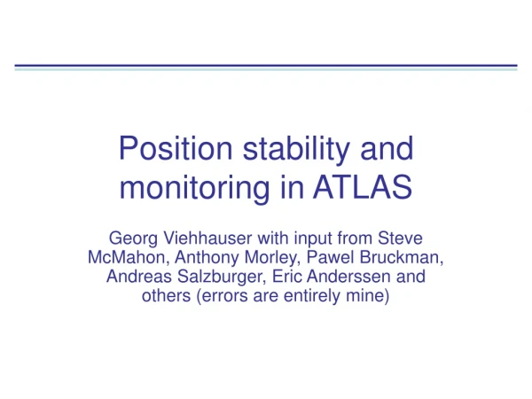
Position stability and monitoring in ATLAS. Georg Viehhauser with input from Steve McMahon, Anthony Morley, Pawel Bruckman, Andreas Salzburger, Eric Anderssen and others (errors are entirely mine). What this talk is about. How do we know where things are?

E N D
Position stability and monitoring in ATLAS Georg Viehhauser with input from Steve McMahon, Anthony Morley, Pawel Bruckman, Andreas Salzburger, Eric Anderssen and others (errors are entirely mine)
What this talk is about • How do we know where things are? • What contribution to this knowledge comes from hardware? • Build tolerances • Structural stiffness • Alignment systems • How do the physicists (tracking and track-based alignment community) convey their needs to the mechanical engineering community • All in the context of ATLAS silicon detectors– what has been done and achieved in the past, and what we plan to do in the future
EC strips: • Individual modules • mounted on carbon-carbon cooling blocks • on YSH-50A/RS3 & Korex sandwich disks Pixel system: • Local supports (bi-staves and sectors) made of UHM CF • On CF cylinders (YS80/EX1515) Structures of the ATLAS silicon detectors Barrel strips: • Individual modules • mounted with CF brackets • on XN50A/RS3 & Ultracor UCF-83-1/4-3.0 sandwich cylinders (one per layer)
…so, what stiffness should our structure have?... …well, make it as stiff as possible. Isambard Kingdom Brunel Does this sound familiar?... (unconvinced)…ok… … and use as little material as possible… …Duh…so how do I know how to trade off one against the other? … Hmm, just design it so that the resonance frequency is above 50Hz… Why?... …because this is line frequency… (goes away, grumbling something about) …proper specifications… Detailed stability definitions did exist in the case of ATLAS (although not everybody seems to have been aware of them)
Strips: Pixel: What was specified From the ATLAS Inner Detector TDR:
And how it ties together So, there was a sequence outlined: • Placement • Metrology during build at various levels • X-ray survey (shoot X-rays as straight lines through the tracker) • Frequency Scanning Interferometry (FSI) system for online deformation monitoring • And then: track-based alignment From overall ATLAS TDR: Emphasis on hardware alignment Tracks provide correction Hardware alignment is starting point for track-based alignment
Width 5mm Height 2.5mm Length 9mm Diameter 2.5mm ATLAS FSI system • A geodetic grid of length measurements between nodes attached to the SCT support structure • All 842 grid line lengths are measured simultaneously using FSI to a precision of <1μm • Only small and passive components within tracker • Allows an absolute length measurement (but only of the grid, tells you nothing about individual modules)
What have we achieved (medium timescale)? This is driven by ‘seismic events’ • Cooling system stops, magnet quenches, power outages, etc… • For example: 19 cooling system stops (16 unscheduled) in 2011 2 month
What we really did Sequence defined in the TDR: • Placement • Significant efforts were spent to place components accurately (for example μm precision in the placement of sensors in strip modules) • It is now commonly understood that a high level of placement accuracy is not required • Metrology during build at various levels • Was done for some components (pixels) but not for others (strips) • X-ray survey (shoot X-rays as straight lines through the tracker) • Cancelled due to time pressure during integration • Frequency Scanning Interferometry (FSI) system for online deformation monitoring • This is installed and running beautifully, however • It’s information is not used actively in the alignment (just used for cross-checks and monitoring of stability) • And then: track-based alignment • This is the main alignment method and has proven to be very powerful • But there are classes of deformations which are more difficult to address than others (‘weak modes’) The most important reason for this change of tack is the excellent stability, which exceeds the levels outlined in the TDR
Weak deformation modes • Deformations which do not result in a significantly increased χ2 of a track fit, but affect other physics-relevant measurement parameters (e.g. vertex position). • Typically these are coherent deformations of larger sections of the tracker. • In track alignment some of these movements can be constrained from • module overlaps (in particular in r due to the closed loop constraint), • with cosmics, • or from higher-order reconstruction (e.g. reconstruction of invariant mass-peaks • Weak modes shifting the positions in φ (in particular curls and twists) have strongest impact on reconstructed momentum • But: weak mode misalignments creep in for any track-based alignment
Example for weak mode deformation Ks mass reconstruction Tracker tilt: Z mass reconstruction Z mass peak
Our approach for the future As a starting point for the design of the HL-LHC ATLAS tracker structures want to define positioning requirements • This clearly is based on experience from current tracker • Input from tracking and track-based alignment communities
Stability requirements for phase II • Short timescale: • No major disturbing events from external causes (magnet ramps, intended or unintended cooling system stops etc.) • From ATLAS experience: ~24h. Corresponds to the timescale of a track-based alignment cycle. • Typical load variations during this timescale are • External vibration (relevant at time scales of up to 1s), • Power fluctuations of the front-end electronics of about 10%, • Temperature variations at any given position of ±1°C. • In present tracker typically a stability of 1µm was achieved during these periods (in rφ) • For future tracker we require the same performance over this timescale. • Medium timescale: • Timescale over which we currently gather enough data to constrain the weak modes (~1 month) • During these periods there are changes of • Temperature variations at any given position of ±3°C, • Relative humidity variations between 10% and 50% at the operating temperature. • In addition (relatively infrequent) external perturbations (‘seismic events’) can occur, which include • Magnet ramps, • Cooling system cycles, • Power and HV cycles, • In the present tracker typically a stability of order of 10µm was achieved during these periods. • For future tracker we require a stability of 5µm everywhere between seismic events, and internal to subsystems at all times • Long timescale: • Stability against relaxation caused by creep, possibly accelerated by irradiation. • The timescale is months to years. • Require that the detector positions satisfy the same criteria as in the original placement requirements 14
Stability under vibration – Miles’ equation • The acceleration response of a 1dim dampened oscillator for constant ASD can be found from Miles’ equation • The displacement response is • And, using the deflection under gravity John W Miles Quality factor Acceleration spectral density
Acceleration spectrum in particle physics experiments • Unfortunately we don’t have a measurement of the ASD in ATLAS yet • This will be done during and after the shutdown next year • But we have a measurement of ASD in STAR, for illustration • This is at 10-8g2/Hz with a single peak at 10-7g2/Hz at about 240 Hz, no indication of line frequency being a particular problem • This is representative for light industrial environment (typically 10-7 to 10-8 g2/Hz) Courtesy of E. Anderssen, H. Wieman
Displacement response for 1d oscillator • Assumes Q = 12.5 • At 10-7g2/Hz resonance frequency must be 50Hz for an RMS displacement of 1μm • And about 25 Hz at 10-8g2/Hz • Does this also apply to 3d object?
Modal participation factor Modal amplitude (normalized) Acceleration density and with Modal masses Multi-modal systems • Displacement for multi-modal system • Modal participation factors • Modal participation factors and mode shapes can be obtained from FEA (or for simple systems analytically) Damping (assumed independent of mode) (This assumes uniform base vibration)
with Example: Euler-Bernoulli beams • Solutions for resonance frequencies Simple CF/foam sandwich like outer pixel stave EI = 13.4Pam4, λ = 0.055kg/m, l = 0.7m
Example: fixed-fixed beam Mode shapes still proportional to √ASD (for constant ASD) Displacement response at different locations
Depends on environment Depends on BC Depends on beam properties Comparison to Miles’ equation • Compare analytical multi-modal analysis with Miles’ equation (taking f0 (1dim) = f1 (multi-modal)) • Miles’ equation underpredicts maximum RMS displacement along beam, but overpredicts everywhere else (including RMS along beam by up to 20%) • Ratios are independent of beam parameters, only depend on BCs • → Miles’ equation still appears to predict beam reasonably well
Damping • Damping is to a large extent driven by the materials • In CF composite structures it’s dominated by the matrix material and the fibre orientation • Typical values in literature for damping in high-modulus CF structures are between ~1-5%, where the lower number is along unidirectional fibres and the upper for larger angles. More complex lay-ups somewhere in between • This results in Q~1/2ζ between 10 and 100 • Larger structures will probably be much stronger damped due to parasitic (non-support) connections (e.g. services)
Thermal load changes • Changes in front-end electronics power consumption • Rate-dependent • In ATLAS reduced by L1 levelling • Different run types (calibrations etc.)? • In ATLAS SCT front-end power constant within 10% (expected to be similar for phase II) • Local variation of front end power changes local temperature according to thermal impedance between source (ASIC) and sink (coolant) • But: in evaporative cooling system a change of load will result in a change of output vapour quality • This will result in a different pressure drop in the return pipework • Typically in evaporative systems the pressure is defined by a remote backpressure regulator or accumulator • So, the evaporation temperature will change on the detector • Any short-term coolant flow variation will have a similar effect
ATLAS phase II positioning requirements Stabililty Constraints on position knowledge {placement and surveys) which alignment community thinks will help constraining weak modes
Summary • The main tool for alignment in ATLAS is track-based alignment • Mechanical engineering should support it • Understanding between these communities is sometimes difficult • The main requirement for track-based alignment is stability • Placement accuracy and assembly surveys are not critical • Our experience from ATLAS is that excellent stability is achievable (particularly short-term) • The dominant disturbances to stability on short timescales are vibrations and thermal load variations • Vibrations are not particularly critical as particle physics experiments are not particularly noisy environments • For an acceleration spectral density of 10-7 g2/Hz the first resonance frequency needs to be above 50 Hz to achieve a stability of 1μm (but not because it’s line frequency…) • Deformations due to thermal load variations should be addressed at the source • Equalize front-end power consumption • Build stable cooling system