Download
1 / 9
90 likes | 214 Views
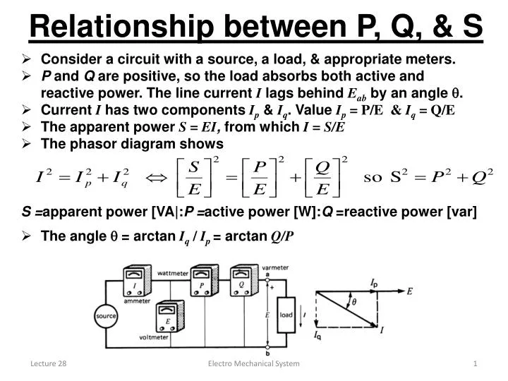
Relationship between P, Q, & S. Consider a circuit with a source, a load, & appropriate meters. P and Q are positive, so the load absorbs both active and reactive power. The line current I lags behind E ab by an angle .

E N D
Relationship between P, Q, & S • Consider a circuit with a source, a load, & appropriate meters. • P and Q are positive, so the load absorbs both active and reactive power. The line current I lags behindEab by an angle . • Current I has two components Ip & Iq. Value Ip = P/E & Iq = Q/E • The apparent powerS = EI, from which I = S/E • The phasor diagram shows • S =apparent power [VA|:P =active power [W]:Q =reactive power [var] • The angle = arctanIq / Ip = arctan Q/P Electro Mechanical System
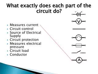
Power factor • The power factor of an ac device or circuit is the ratio of the active power P to the apparent power S. given by the equation: • power factor =P / S = EIP / EI = IP / I = cos • Where: • P = active power delivered or absorbed by circuit or device [W] • S = apparent power of the circuit or device [VA] • Power factor is expressed as a simple number, or a percentage. • The power factor can never be greater than unity (or 100 percent). • The power factor of a resistor is 100 percent because the apparent power it draws is equal to the active power. • The power factor of an ideal coil having no resistance is zero, because it does not consume any active power. • The power factor of a circuit or device is simply a way of stating what fraction of its apparent power is real, or active, power. • In a single-phase circuit the power factor is also a measure of the phase angle between the voltage and current • If we know the power factor, we can calculate the angle. The power factor is said to be lagging or leading. Electro Mechanical System
Power triangle • Relationship S2 = P2 + Q2 is right-angle triangle, known as a power triangle. • Following rules apply: • Active power P absorbed by a circuit or device is considered to be positive and is drawn horizontally to the right • Active power P that is delivered by a circuit or device is considered to be negative and is drawn horizontally to left • Reactive power Q absorbed by a circuit or device is considered to be positive and is drawn vertically upwards • Reactive power Q that is delivered by a circuit or device is considered to be negative and is drawn vertically downwards • The concept of the power triangle is useful when solving ac circuits that comprise several active and reactive power components. Electro Mechanical System
Sources and loads • A resistor and capacitor are connected to the source. • Capacitor acts as a reactive source. • A wattmeter connected into the circuit will give a positive reading P = Elp watts, but a varmeter will give a negative readingQ = EIq . • Source G delivers active power P but receives reactive power Q. • Two powers flowing in opposite directions over the same line. • An electrical outlet can act not only as an active or reactive source, but it may also behave as an active or reactive load. • It depends upon the type of device connected to the receptacle. Electro Mechanical System
System with several loads • Consider, a group of loads connected in an unusual way to a 380 V source . • We wish to calculate the apparent power absorbed & current supplied by source. • We simply draw a block diagram of the individual loads, indicating the direction of active and reactive power flow • Add all the active powers in a circuit to obtain the total active power P. • We can add the reactive powers to obtain the total reactive power Q. • Total apparent power S is then found by: • Adding reactive powers, we assign a +ve value to those that are absorbed by the system and a –ve value to those that are generated (such as by a capacitor) Electro Mechanical System
System with several loads • Similarly we assign a +ve value to active powers that are absorbed and –vevalue to those that are generated (by an alternator) • we cannot add the apparent powers to obtain the total apparent power S. Add them only if their power factors are same • Let us now solve the circuit : • 1. Active power absorbed by the system: • P = (2 + 8 + 14) = +24 kW • 2. Reactive power absorbed by the system: • Q1 = (5 + 7 + 8) = +20 kvar • 3. Reactive power supplied by the capacitors: • Q2 = (–9 –16) = – 25 kvar • 4. Net reactive power Q absorbed by the system: • Q = ( + 20 –25) = – 5 kvar Electro Mechanical System
System with several loads • Apparent power of the system: • 6. Because the 380 V source furnishes the appaentpower, the line current is • I = S/E = 24 500/380 = 64.5 A • 7. The power factor of the system is • cosL = P/S= 24/24.5 = 0.979 (leading) • The 380 V source delivers 24 kW of active power, but it receives 5 kvar of reactive power. • This reactive power flows into the system of the electrical company, where it is available to create magnetic fields. • The magnetic fields may be associated with distribution transformers, transmission lines, relays etc. Electro Mechanical System
System with several loads • Let us make power triangle for the system. • It is the graphical solution to our problem. • Starting with the 5 kvar load, we move from one device to the next around the system. • We draw the magnitude and direction (up, down, left, right) of each power vector. • At the end, we can draw a power vector from the starting point to the end point. • Vector having a value of 24.5 kVA. • The horizontal component of this vector has a value of 24 kW and, because it is directed to the right, we know that it represents power absorbed by the system. • The vertical component of 5 kvar is directed downward, so it represents reactive power generated by the system. Electro Mechanical System
Reactive power without magnetic fields • Loads sometime absorb reactive power without creating any magnetic field at all. • This can happen in electronic power circuits when the current flow is delayed by means of a rapid switching device. • Consider, a circuit in which a 100 V, 60 Hz source is connected to a 10 Ω resistive load by means of a mechanical switch. • The switch opens and closes its contacts so that current only flows during the latter part of each half cycle. • This forced delay causes the current to lag behind the voltage. • If we connect a wattmeter and varmeter, they would read +500 W and + 318 var. • This corresponds to a lagging power factor (sometimes called displacement power factor) of 84.4 percent. • Reactive power is associated with the rapidly operating switch rather than with the resistor itself. Electro Mechanical System