Download

1 / 7
70 likes | 229 Views
Lab 5 Multiplexer and 7-Segment Display. Module M7.3. EXPERIMENT 5: Multiplexer and 7-Segment Display. PRE-LAB. 1. Study text Sec. 6.5, Code Converters , pages 143-152.

E N D
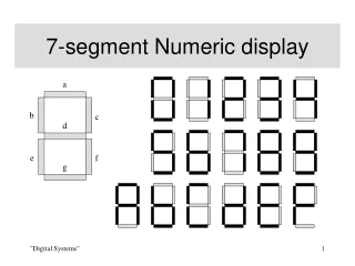
Lab 5Multiplexer and 7-Segment Display Module M7.3
EXPERIMENT 5: Multiplexer and 7-Segment Display PRE-LAB 1. Study text Sec. 6.5, Code Converters, pages 143-152. 2. Write an ABEL program called MuxDisp that includes a 4-line 2x1 MUX with inputs X and Y and output Z (see Lab 4) plus a 7-segment decoder as described in the lecture module M7.2. The input X = [X3..X0] should be connected to switches S1 (the left-most 4 switches) and the input Y = [Y3..Y0] should be connected to switches S2 (the right-most 4 switches). The eight LEDs should record the settings of the corresponding eight switches. The output of the multiplexer, Z = [Z3..Z0], is the input to the 7-segment decoder. The select line of the multiplexer, S, should be connected to the pushbutton switch. Connect the pushbutton switch to the decimal point of the 7-segment display. Complete the following set of test vectors and add them to the end of your ABEL program.
test_vectors ([X,Y,S] -> Z) [12,0,0] -> ; [8,4,1] -> ; [13,1,0] -> ; [9,5,1] -> ; [15,3,0] -> ; [11,7,1] -> ; [14,2,0] -> ; [10,6,1] -> ; Print out a copy of the file MuxDisp.abl.
LAB 1. Create a directory called <your name> under C:\CSE171 on the computer you are using in the lab. Create a new project called Lab5 using the Xilinx Project Navigator program. (See the Lab 2 tutorial for details.) Add your program MuxDisp.abl to the project by using Project->Add Copy of Source… on the Project Navigator toolbar. Compile your program by double-clicking Generate Programming File.
2. Select MuxDisp-vectors in the Sources in Project window. Double-click Generate Blif Simulation Report under Simulation Reports in the Processes for Current Source window. Double-click View Blif Simulation Report under Generate Blif Simulation Report. If there are no errors, print out this Blif Simulation Report. 3. Select MuxDisp.abl in the Sources in Project window. Program the Xilinx XC9508PC84 CPLD on the PLDT-1 board by double-clicking Configure Device (iMPACT) and then right-clicking on the picture of the Xilinx chip.
4. Test your circuit by setting the toggle switches on the PLDT-1 digital logic trainer board to the following values. For each value, record the binary values displayed in LEDs 5 to 8 and the hex values displayed in the 7-segment display with the push-button switch both released and depressed. Report these results in your lab report. push button released push button depressed toggle switch 7-segment 7-segment valuesdisplaydisplay '1100 0000' ____ ____ '1101 0001' ____ ____ '1111 0011' ____ ____ '1110 0010' ____ ____ '1010 0110' ____ ____ '1011 0111' ____ ____ '1001 0101' ____ ____ '1000 0100' ____ ____
5.Demonstrate your completed multiplexer and 7-segment display circuit to your lab instructor and obtain your lab instructor's signature for your work on the .abl listing for the program MuxDisp.abl. 6. Include the following in the lab report: a. A listing of your file, MuxDisp.abl. b. A listing of the Blif Simulation Report. c. A copy of the file, PLDT1PinOuts.doc. d. A copy of the results from the table in Part 4 above. 7. Delete the directory C:\CSE171\<your name> that you created at the beginning of this lab.