Download

1 / 27
310 likes | 784 Views
Digital Outputs 7-Segment Display. Khaled A. Al- Utaibi alutaibi@uoh.edu.sa. Agenda. Introduction Types of 7-Segment Display Common Cathode Common Anode Displaying Digital Digits Driving 7-Segment Display BCD to 7-Segment Display Decoder Interfacing 7-Segment Display to Arduino.

E N D
Digital Outputs7-Segment Display Khaled A. Al-Utaibi alutaibi@uoh.edu.sa
Agenda • Introduction • Types of 7-Segment Display • Common Cathode • Common Anode • Displaying Digital Digits • Driving 7-Segment Display • BCD to 7-Segment Display Decoder • Interfacing 7-Segment Display to Arduino
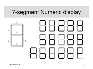
Introduction • The 7-segment display, consists of seven LEDs arranged in a rectangular fashion as shown in the Figure. • Each of the seven LEDs is called a segment.
Introduction • Each one of the seven LEDs in the display is given a positional segment which is controlled by one pin. • These LED pins are labeled a, b, c, d, e, f, and g representing each individual LED. • The other LED pins are connected together and wired to form a common pin. • By forward biasing the appropriate pins of the LED segments, some segments will be light and others will be dark allowing the desired character pattern of the number to be generated on the display. • This allows us to display each of the ten decimal digits 0 through to 9 on the same 7-segment display.
Types of 7-Segment Display • The displays common pin is generally used to identify which type of 7-segment display it is. • As each LED has two connecting pins, one called the “Anode” and the other called the “Cathode”. • Therefore , there are two types of LED 7-segment display: • (1) Common Cathode (CC) • (2) Common Anode (CA)
Common Cathode • In the common cathode display, • all the cathode connections of the LED segments are joined together to logic “0″ or ground. • The individual segments are illuminated by application of a “HIGH”, or logic “1″ signal via a current limiting resistor to forward bias the individual Anode terminals (a-g).
Common Anode • In the common anode display, • all the anode connections of the LED segments are joined together to logic “1″. • The individual segments are illuminated by applying a ground, logic “0″ or “LOW” signal via a suitable current limiting resistor to the Cathode of the particular segment (a-g).
Displaying Digital Digits • Depending upon the decimal digit to be displayed, the particular set of LEDs is forward biased. • The various digits from 0 through 9 can be displayed using a 7-segment display as shown.
Table 1: Display decimal digits using the 7-segments A F B G E C D
Driving a 7-Segment Display • Although a 7-segment display can be thought of as a single display, it is still seven individual LEDs within a single package and as such these LEDs need protection from over-current. • LEDs produce light only when it is forward biased with the amount of light emitted being proportional to the forward current. • This means that an LEDs light intensity increases in an approximately linear manner with an increasing current. • So this forward current must be controlled and limited to a safe value by an external resistor to prevent damaging the LED segments.
Driving a 7-Segment Display • The forward voltage drop across a red LED segment is very low at about 2-to-2.2 volts. • To illuminate correctly, the LED segments should be connected to a voltage source in excess of this forward voltage value with a series resistance used to limit the forward current to a desirable value. • Typically for a standard red colored 7-segment display, each LED segment can draw about 15mA to illuminated correctly, so on a 5 volt digital logic circuit, • the value of the current limiting resistor would be about 200Ω (5v – 2v)/15mA, or • 220Ω to the nearest higher preferred value.
Driving a 7-Segment Display • So to understand how the segments of the display are connected to a 220Ω current limiting resistor consider the circuit below.
Driving a 7-Segment Display • In this example, • the segments of a common anode display are illuminated using the switches. • If switch a is closed, current will flow through the “a” segment of the LED to the current limiting resistor connected to pin a and to 0 volts, making the circuit. • Then only segment a will be illuminated. • If we want the decimal number “4″ to illuminate on the display, then switches b, c, f and g would be closed to light the corresponding LED segments.
BCD to 7-Segment Decoder • The 7-segment Display is usually driven by a special type of integrated circuit (IC) known as a BCD to 7-segment decoder as shown in the figure.
BCD to 7-Segment DecoderThe 4543 BCD to 7-Segment Decoder • The 4543 is a BCD to 7-segment latch/decoder/driver. • Its function is to convert a BCD digit into signals which will drive a 7-segment display. • Inputs: • four address inputs (D0 to D3), • an active LOW latch enable input (LE), • an active HIGH blanking input (BL), • an active HIGH phase input (PH) • Outputs: • seven buffered segment outputs (Qa- Qg).
BCD to 7-Segment DecoderThe 4543 BCD to 7-Segment Decoder • The functions of the three control inputs PH, BL and LE are as follows: • The phase (PH) input is used to reverse the function table phase. • The blanking (BL) input is used to blank (turn off) the display. • The latch enable (LE) input is used to store a BCD code.
Table 2: Function table of the 4543 BCD to 7-segment decoder
Interfacing 7-Segment Display to Arduino • The 7-Segment Display (shown in Figure below) can be interfaced to the Arduino Uno Board as shown in the next two slides. Pin configuration of the 7-Segment display with common cathode G F G1 A B E D G2 C DP
BCD Counter Example • Interface the 7-Segment Display to the Arduino Uno Board as in the previous figures. • Then, write a program to display a BCD counter (counting from 0 – to – 9) with a period of 1 second (every count takes 1 second) as shown in the figure below.
BCD Counter ExampleProgram Main Parts • The required program consists of three main parts: • (1) Output Pins Configuration • (2) Counter Logic • (3) BCD Digit Display
BCD Counter ExampleOutput Pins Configuration • In this part, pins 0 to 4 are defined as output pins to control illumination of the 7 segments: • Pins 0-3: control the address inputs (Dd, Dc, Db, Da) of the 4543 decoder • Pin 4: control the Latch Enable (LE) of the 4543 decoder. publicvoid setup(){ // configure pins 0-4 as output pins for (inti = 0; i < 5; i++) { pinMode(i, OUTPUT); } }
BCD Counter ExampleCounter Logic • In this part, a FOR loop is used to implement the one-digit BCD counter logic with 1 second delay. public void loop(){ // for every bcd digit (0-9) do the following for (int digit = 0; digit < 10; digit++) { // (1) call displayDigit function displayDigit(digit); // (2) wait for 1 second delay(1000); } }
BCD Counter ExampleBCD Digit Display • In this part, a function is used to display the given decimal digit (BCD code) as follows: • (1) Set the LE line of the 4543 decoder HIGH to write the received BCD code into the 4543 decoder. • (2) for each bit in the received BCD code do the following: • (a) Determine the value of the bit (0 or 1). • (b) Set the corresponding output pin (HIGH or LOW) accordingly. • (3) Set the LE line of the 4543 decoder LOW to latch (store) the received BCD code into the 4543 decoder
// displays a given BCD digit on a 7-segment display voiddisplayDigit(int digit) { // (1) set LE line high to write the received BCD code into the decoder. digitalWrite(4, HIGH); // (2) for each bit in the received BCD code do the following for (inti = 0; i < 4; i++) { // (a) determine the value of the bit (0/1) intbitValue = bitRead(digit, i); // (b) set the corresponding output pin (0-3) (HIGH/LOW) accordingly digitalWrite(i, bitValue); } // (3) Set the LE line low to store the received BCD code into the decoder digitalWrite(4, LOW); }
BCD Counter ExampleThe bitRead() Function • The bitRead() function reads a bit of a number. • Syntax: • bitRead(x, n) • Parameters: • x: the number from which to read. • n: which bit to read, starting at 0 for the least-significant (rightmost) bit • Returns: • the value of the bit (0 or 1).