Download
1 / 40
400 likes | 489 Views
GENERATOR HEAT RECOVERY CONSIDERATIONS IN ARCTIC VILLAGE APPLICATIONS LCDR William Fraser, P.E. Who We Are. Alaska Native Tribal Health Consortium Division of Environmental Health & Engineering June 2011. ANTHC. Non-profit, statewide organization

E N D
GENERATOR HEAT RECOVERY CONSIDERATIONS IN ARCTIC VILLAGE APPLICATIONSLCDR William Fraser, P.E.
Who We Are Alaska Native Tribal Health ConsortiumDivision of Environmental Health & Engineering June 2011
ANTHC • Non-profit, statewide organization • Provides a range of medical and community health services for more than 125,000 Alaska Natives. • Part of the Alaska Tribal Health System, which is owned and managed by the 229 federally recognized tribes in Alaska and by their respective regional health organizations.
ANTHC History • 1970s-1990s: Regional health organizations in Alaska • Passage of P.L. 105-83 established ANTHC, the only THO established by statute • December 1997: ANTHC incorporated as non-profit 501(c)(3) • June 1998: Initial contract with IHS.
ANTHC History • October 1998: Contract expanded to include Environmental Health & Engineering • October 1998: ANTHC becomes a P.L. 93-638 Title III Self-Governance entity, signing the Alaska Tribal Health Compact
DEHE Designs and Constructs Health and Sanitation Facilities Provides operations support Monitors & develops standards for mitigating climate change impacts Health impact studies Environmental Grants & training
What does this have to do with Heat Recovery? Hospitalizations are 5 times higher in communities w/o piped water & sewer. Typical Fuel consumption for an Arctic WTP w/ piped water & sewer: 8000-25,000 Gal / Year Fuel Oil Fuel Prices between $6.00 & $8.00 / Gal. and rising. Heat recovery can help make it affordable.
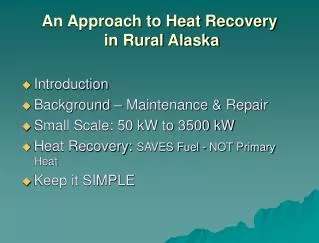
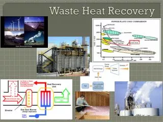
HEAT RECOVERY FROM POWER PLANTS • 2 basic types: • Jacket recovery • Stack recovery • Small Scale: 50 KW to 3500 KW • Ideal for space heat and process heat • Considered a fuel saver, not a primary source of heat.
ADVANTAGES OF HEAT RECOVERY • Very green- reduces carbon footprint. • Can dramatically increase the economic viability of a community water system. • Adds additional redundancy to the building heating system.
DISADVANTAGES OF HEAT RECOVERY • Requires an agreement with the power utility, often with a charge for waste heat. • Usually increases the complexity of the heating system, especially in Washeterias. • Requires additional maintenance and coordination between power utility and building owner.
SO YOU WANT TO BE GREEN • What do you need to know before you start? • Estimating available waste heat • Deciding on a heat recovery strategy • Selecting system components
WHAT DO YOU NEED TO KNOW BEFORE YOU START? • Who owns the generators and what are their conditions? • Do you have a viable path between the waste heat source and the building? • What type of building are you serving? • Are there other buildings served by the waste heat? • What type of monitoring do you want? • Who is going to maintain it?
ESTIMATING AVAILABLE WASTE HEAT QA = QGEN – QPIPE - QO QA: Minimum available waste heat for your building QGEN: Average generator output during peak heating season (typically much less than rated capacity) in BTUs / Hour QPIPE: Heat loss from distribution piping during peak heating season. Typically about 50-60 BTUH / LF QO: Heat used by other buildings on the waste heat system (sometimes this is prioritized by order of connection, so be careful)
HEAT RECOVERY RULES OF THUMB: • Generator Output: 1/3 Electricity, 1/3 Jacket heat, 1/3 Stack loss • 1300-2000 BTU / KW-Hr (Available Jacket Heat) • 100,000 BTU delivered heat = 1 gallon of diesel • Annual Fuel Saved = .3 x Power plant annual fuel used x 0.6 • Pumping Energy Costs <= 10% Fuel Value
BREAK EVEN TEMPERATURE DIFFERENCE PPUMP x CE x 100 PPUMP x CE x 100 TBR = + COIL x UAHX 900 x GPM x COIL TBR: Break even temperature difference between Generator Heating Supply and Building Heating Return (Deg F) PPUMP: Pump power (W) CE: Electrical cost ($ / kWh) COIL: Fuel cost ($ / Gallon) (80% efficiency assumed) UAHX:Heat exchanger U factor multiplied by HX area (BTU/ Hr x Deg F) GPM: Heat exchanger glycol flow rate (GPM) (This formula only applies in special case of counterflow HX with matching flow rates and sufficient heating demand to use all of the waste heat)
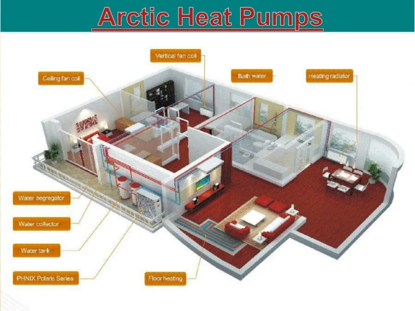
ESTIMATING WASTE HEAT DEMAND QD = QBLG + QPROC QD: Waste heat demand (typically does not include dryers) QBLG: Building envelope heat losses (must engineer heating system for lower temperatures than typical heating systems) QPROC: Heat required by process systems (includes circulation loops, raw water heat add, storage tanks, etc. This is where waste heat really shines)
SELECTING A HEAT RECOVERY STRATEGY • Direct heat add to potable water: • Double wall shell and tube, independent of boiler system (Kiana) • Small system with single boiler: • Pipe heat exchanger in series with boiler (Chenega Bay) • Large system with multiple boilers: • Pipe heat exchanger in primary / secondary arrangement (Kwigillingok)
WASTE HEAT CONTROLLER • Turns on at 8 Deg F difference • Turns off at 4 Deg F difference • Built in HOA switch. • Provides 1p/2t switch which can handle a 1 HP pump.
DESIGN COMMENTS • Use Brazed Plate or Plate / Frame heat exchangers • Provide controls to ensure heat is not transferred back to generator cooling system. • Provide controls to minimize electric power consumption • Provide BTU monitoring if being billed by local utility • Provide pressure relief on pipeline • Provide strainers on both sides of heat exchanger (reduces cleaning of heat exchanger). • Provide air separator on pipeline side of system. • Provide glycol system monitoring and makeup. • Provide expansion compensation • Don’t use HDPE pipe. Copper, Steel, PEX, Stainless steel. • Monitor pipeline for leaks and pressure.