Download
1 / 108
1.12k likes | 1.47k Views
6.1 Documentation standards The type of documentation depends on system complexity and the engineering and manufacturing environments, a documentation package should generally contain at least the following six item: Specification ( I/O, function ) Block diagram ( pictorial description )

E N D
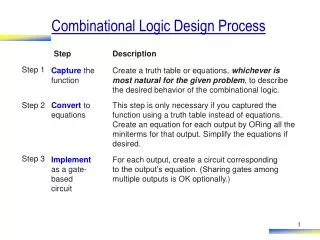
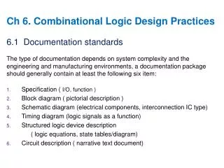
6.1 Documentation standards The type of documentation depends on system complexity and the engineering and manufacturing environments, a documentation package should generally contain at least the following six item: • Specification ( I/O, function ) • Block diagram ( pictorial description ) • Schematic diagram (electrical components, interconnection IC type) • Timing diagram (logic signals as a function) • Structured logic device description • ( logic equations, state tables/diagram) • Circuit description ( narrative text document) Ch 6. Combinational Logic Design Practices
6.1.1 Block Diagrams Control Signal
6.1.2 Gate Symbols A B F F = (A’ * B’)’ = A’’ + B’’ = A + B
6.1.5 Bubble-to-Bubble Logic Design (A * SEL)’ = ((A*SEL)’ * (B * SEL’)’)’ = A*SEL + B*SEL’ (Hard to read) (B * SEL’)’ (Easy to read)
6.1.8 Buses / 16 / 8 / 8
6.2 Circuit Timing Most digital systems are sequential circuits that operate step-by-step under the control of a periodic clock signal, and the speed of the clock is limited by the worst-case time that it takes for the operations in on step to complete. Thus digital designers need to be keenly aware of timing behavior in order to build fast circuits that operate correctly under all conditions • Timing Diagrams • Propagation Delay • Timing Specifications • Timing Analysis • Timing Analysis Tools
6.2.1 Timing Diagrams Causality
6.2.1 Timing Diagrams Uncertain transition
Vin Vout tpHL tpLH 6.2.2 Propagation Delay - maximum/minimum delay - typical : average ex) 99% good IC, CKT with 100 IC • worst-case delay (1 - 0.99100 ) x 100 = 63% ( would not work) = sum of worst case delay through individual component = max. delay
6.2.3 Timing Specifications The timing specification for a device may give minimum, typical, and maximum values for each propagation-delay path and transition direction
‘ n X m PLA with P product term ‘ 2n = true or complement of input 6.3 Combinational PLDs • 6.3.1 Programmable Logic Arrays : PLA # of inputs (n) # of outputs (m) # of product term (P) Contains p AND gates(2n-input) and m OR gates(p inputs) • 2n-input AND gate -> p • P-input OR gate -> m • → PLA fuses are ‘x’ in the figure and nonvolatile memory cells. • → They are programmed.
6.3.1 Programmable Logic Arrays O1 = I1·I2 + I1´·I2´·I3´·I4´ O2 = I1·I3´ + I1´·I3·I4 + I2 O3 = I1·I2 + I1·I3´ + I1´·I2´·I4´ P1 P2 = I1*I2 + I1’*I2’*I3’*I4’
6.3.3 Generic Array Logic Devices • [Ex-2] GAL16L8 : Fig 27 • input output • XOR gate between OR and inverter • output polarity = if fuse -> intact, XOR = AB+AB (B =0) = A (PASS) -> blown , XOR = AB+AB (B=1) = A ( inverting)
6.3.5 CMOS PLD Circuits i) AND-OR diode logic 5V A A X = A+B X = A·B B B • fusible link, high voltage ( 10~30V ) -> OFF • masked programmed PLD -> ROM
6.3.5 CMOS PLD Circuits ii) CMOS PLD CKTs < AND plane > < OR plane >
6.3.5 CMOS PLD Circuits iii) erasable PLD accumulated charge at high volt(25V) ultra-violet light -> erase Ex) PLD writer : PLD programmer and testing (test vector generation) floating gate ( change storage device) 10 years -> 70% decay
6.4 Decoder A decoder is a multiple-input, multiple-out logic circuit that converts coded inputs into coded outputs, where the input and output codes are different • Binary Decoders • Logic Symbols for Larger-Scale Elements • The 74x138 3-to-8 Decoder • Decoders in VHDL
6.4.1 Binary Decoder - 2n decoder n bit binary input code 1 out of 2n output code
6.4.1 Binary Decoder P.52 [Fig6] Gary code
6.4.3 The 74x138 3-to-8 Decoder Y5 = G1*G2A*G2B*CB’A Enable Select
6.4.3 The 74x138 3-to-8 Decoder G2A = G2A_L’, G2B = G2B_L’, Y5 = Y5_L’ Y5 = G1 * G2A * G2B * CB’A Y5_L = G1’ + G2A_L + G2B_L +C’ + B + A’
6.4.3 The 74x138 3-to-8 Decoder • 3 enable inputs : G1, G2A , G2B • ex) Y5 = G1· G2A · G2B·A·B·C Y5´ = (G1· G2A · G2B·A·B·C)´ = G1´+ G2A + G2B+A+B+C because of inversion bubble on Y5
6.4.4 Cascading Binary Decoders higher order decoder : tree decoding • 4 select inputs : N0 N1 N2 N3 + 1 enable EN • SN74154 ( 1 out of 16 decoder )
6.4.4 Cascading Binary Decoders 3LSBs 2MSBs N4*N3 = 00,Y0’ = L N4*N3 = 01,Y1’ = L N4*N3 = 10,Y2’ = L N4*N3 = 11,Y3’ = L
6.4.6 Decoder in VHDL Entity : Simply a declaration of a module’s inputs and outputs Architecture: a detailed description of the module’s internal behavior or structure
6.4.6 Decoder in VHDL When A = 010, then Y_L_i = 11011111 When G1*G2A’’*G2B’’ = G1*G2A_L’*G2B_L’
6.4.6 Decoder in VHDL Active-level handling
6.4.6 Decoder in VHDL Instead of Table 6-17 Dataflow definition, Behavior Model uses a process and sequential statements
6.4.6 Decoder in VHDL Page268 Table5-25 Convert std_logic_vector to integer
6.5 Encoder A decoder’s output code normally has more bits than its input code. If the device’s output code has fewer bits than the input code, the device is usually called an encoder • Priority Encoders • The 74x148 Priority Encoder • Encoders in VHDL
6.5.1 Priority Encoders = I1 + I3 + I5 + I7 = I2 + I3 + I6 + I7 = I4 + I5 + I6 + I7
6.5.1 Priority Encoders - 2n inputs each indicates a ‘request’ for service (=interrupt request) - priority encoder each request has a priority • ex) 8-to-3 encoder : 74x148 (I7 = highest priority) idle : if no input
6.5.2 The 74x148 Priority Encoder • logic symbol : · EI : enable input · Gs : assert if Enable and more than 1 input assert (group select) · E0 : enable output : connect to EI input of another 148