Download
1 / 21
210 likes | 410 Views
CAD Import, Partitioning & Meshing. J.Cugnoni LMAF / EPFL 2009. CAD Model Structure. Vertices (0D): Coordinates & coordinate system Edges (1D): several Vertices => line / curve Surfaces (2D): closed loop of edges (shared vertices), parametric 2D space, normal = orientation

E N D
CAD Import, Partitioning & Meshing J.Cugnoni LMAF / EPFL 2009
CAD Model Structure • Vertices (0D): • Coordinates & coordinate system • Edges (1D): • several Vertices => line / curve • Surfaces (2D): • closed loop of edges (shared vertices), parametric 2D space, normal = orientation • Volumes (3D): • a closed set of surfaces (shared edges), unified normal orientation
CAD Example 3D CAD volume: all edges are shared between boundary faces => no « free » edges => surface is closed => it’s a volume!
CAD import in ABAQUS / CAE • Several formats are supported by Abaqus CAE: • STEP : universal file format, good for volumes & assemblies • IGES : universal file format, good for surfaces, ok for volumes • SAT : ACIS, native geometry format of CAE, good for nearly everything • CATPart: CATIA v5 format, can be imported with a specific module (1 licence) • Always check the geometry: • Free edges / invalid entities (tools => query => geom. diagnostic) • If free edges: stitch the surfaces (tools => geom. repair => part => stitch) • If meshing problems: convert to « precise » (tools => geom. repair => part => convert to precise) • Check the dimensions / units !! • If you have problems with geometric operations (like partition), try to Convert to Precise and Convert to Analytical representation
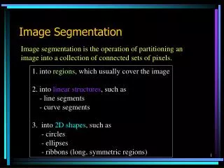
Meshing: basic principle Mesh generation in 3D is based on the same hierarchy as the CAD model: • 1D: meshing of the edges, starting from a user-defined element size / distribution • 2D: propagation of 1D mesh to 2D surface; structured or free (advancing front or medial axis). • 3D: propagation of 2D mesh to the 3D volume; structured, semi-structured (sweep), free
1D Meshing algorithms • Method: • Use the curvilinear parameter to distribute nodes along edges => create 1D elements • Definition: • Constant size: number of elements on edge or element size • Variable size: number of elements and bias • Bias = ratio of largest to smallest elem. size • Pick the edge close to the end to be refined
1D Meshing algorithms Constant element size Biased element size distribution Default (global) element size
Meshing algorithms 2D • Methods: • Propagate 1D mesh on the surface • Curved surface: • Nearly planar: use projection on the best plane • General: mesh in Parameter space • Algorithms: • Structured / mapped meshing • Delaunay triangulation • Advancing front meshing • Medial axis • Definition: • Just select the meshing algorithm • Automatically inherits the mesh size from the edges
Mapped meshing algorithms 2D Mapped meshing (works for surfaces having 3 to 5 corners)
Free meshing algorithms 2D Advancing front meshing Medial axis meshing
Meshing algorithms 3D • Methods: • Propagate 2D mesh in the volume • Algorithms: • Structured / mapped meshing : • map volume to a simple case (hexa) • Semi-structured: • « extrusion » / « sweep » of a free 2D mesh (tri or quad) • Generates either hexa or prisms (wedges) • Free meshing: • Delaunay or Advancing Front tetrahedralization • Definition: • Just select the meshing algorithm • Automatically inherits the mesh size from the surfaces & edges
Mapped meshing algorithms 3D Mapped meshing for hexa: « simple » 3D primitives here 1/8 of a sphere Mapped meshing for hexa: any extrusion of mapped quad. mesh
Sweep meshing algorithms 3D Sweep meshing for wedges : free tri. mesh + extrusion Sweep meshing for hexa.: free quad mesh + extrusion
Free meshing algorithms 3D Free tetrahedral meshing: free advancing front 2D meshing + 3D adv. front tetrahedralization the most general meshing algorithm in Abaqus/CAE
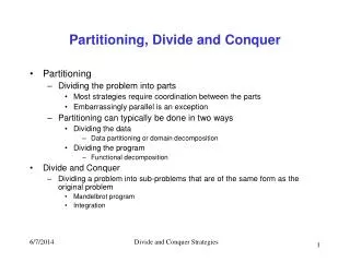
Partitioning • Goal • Decompose the geometry into simpler volumes / faces • Method: • Cut edges, faces or volumes by planes, extrusions, sketch… • Useful to: • Use structured or sweep meshing on certain region of the part • Enhance mesh quality & assign local refinements • Create new faces / edges for boundary conditions or output • Drawback: • If not used correctly: create a lot of small faces and edges => generate very small elements of bad quality Example: see demo & tutorial
CAD & Meshing: continuity problem • Continuous Displacement field => need congruent mesh on the boundaries with shared nodes at the interface • Continuous mesh if and only if shared face or edge => When working with “imported” geometry, need to « merge » boundary faces & edges!! => always check for “Free edges” !! • Incompatible meshing methods can create “hanging” nodes or displacement jumps which are not linked across boundary; for example, linear to quadratic or tetra to hexa transitions are not “compatible” => discontinuous displacement • If not possible to have shared boundaries, one need to impose displacement compatibility through kinematic constraints => additional equations (to avoid whenever possible!!)
Hanging nodes!! Linear Hexahedral mesh Quadratic Tetrahedral Mesh Linear Quadrangular faces Quad. Triangular faces Incompatible Meshes Tetrahedral mesh regions can only be linked to prismatic (wedge) regions. Prismatic regions can be linked to both hexa (along structured faces) and tetra.
Mesh quality • Criteria • Geometry : Distortion ,aspect ratio, minimum angle, maximum angle, … • FE-based: jacobian • Influence: • Low quality = bad mesh convergence • Large stress field discontinuities • Some elements may « lock » for high aspect ratio • Create numerical « round-off » errors & singularities • May completely « crash » the solver if jacobian is negative ! • Advice: • It is usually better to have « good quality » quadratic tetrahedra than « highly deformed » hexahedra !! • Small edges & nearly tangent junction surfaces can be problematic because they require too small or too sharp elements => use virtual topology
CAD & Meshing: advices • In CAD: • Create CLEAN parts for FEA: • Avoid creating smallsurfaces & edges • Avoid « tangent » connections (very small angles) • Try to minimize the number of faces present in the model • Prefer a single « sweep » / « loft » to complex cut / extrude operations (=> can use structured meshing) • Remove unsignificant geometric details: • ask yourself what is important (abstraction) for the goal of the modelling !!! • Typical details: fillets / chamfers, small holes, unsignificant components (bolts & nuts, rivets) For complex parts / assemblies, it is usualy very time consuming to try to « fix » the geometry & meshing problems, you should better completely reconstruct a clean 3D CAD model just for FE analysis
CAD & Meshing: advices • In FEA pre-processor / mesher: • Always check imported geometry (free edges?) • If necessary: repair geometry or try a different format • Partition to create simpler volumes ( symmetries ? ) • Choice of meshing method (if possible): Hex structured > Hex swept > Wedges swept > Tetra free • Use compatible meshes at the interface !!! • Check mesh quality: at least no Analysis Error • Define local refinements where necessary • Use virtual topology if necessary