Download
1 / 87
870 likes | 902 Views
Single phase motors are very widely used in home, offices, workshops etc . as power delivered to most of the houses and offices is single phase. In addition to this, single phase motors are reliable, cheap in cost, simple in construction and easy to repair.

E N D
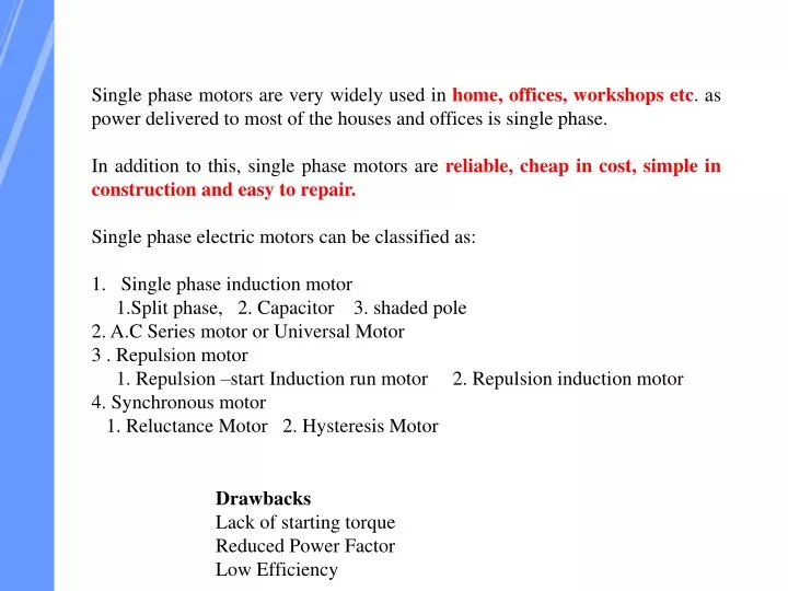
Single phase motors are very widely used in home, offices, workshops etc. as power delivered to most of the houses and offices is single phase. • In addition to this, single phase motors are reliable, cheap in cost, simple in construction and easy to repair. • Single phase electric motors can be classified as: • Single phase induction motor • 1.Split phase, 2. Capacitor 3. shaded pole • 2. A.C Series motor or Universal Motor • 3 . Repulsion motor • 1. Repulsion –start Induction run motor 2. Repulsion induction motor • 4. Synchronous motor • 1. Reluctance Motor 2. Hysteresis Motor Drawbacks Lack of starting torque Reduced Power Factor Low Efficiency
Principle of Operation of Induction Motor In principle of operation of induction motor, rotating magnetic field rotates at synchronous speed interacts with rotor , this will produce torque that will make the rotor rotates at mechanical speed. In three-phase induction motor, the rotating magnetic field is generated by applying three currents shifted by 120 degrees to three windings also shifted by 120 degrees. In single-phase induction motor, there are many types based on method of starting, these types are:
1 3 3 Principle of Operation of Induction Motor Split-phase induction motor. 2 Capacitor start induction motor. Permanent-split capacitor motor. In this type the auxiliary winding and the capacitor are connected from the motor after starting Capacitor start capacitor run motor. 4 In this type two capacitors are used with the auxiliary winding, one for starting and the other during start and run.
Why is Three Phase Induction Motor Self Starting? In three phase system, there are three single phase line with 120° phase difference. So the rotating magnetic field is having the same phase difference which will make the rotor to move. If we consider three phases a, b and c, when phase a is magnetized, the rotor will move towards the phase a winding, in the next moment phase b will get magnetized and it will attract the rotor and than phase c. So the rotor will continue to rotate. Why Single Phase Induction Motor is not Self Starting? When Single phase supply is fed to the stator winding, it produces only an alternating flux only i.e. one which alternates along one space axis only. Due to this starting torque is zero. Hence motor does not rotate.
Single Phase Induction Motor The single-phase induction machine is the most frequently used motor for refrigerators, washing machines, clocks, drills, compressors, pumps, and so forth.
Single Phase Induction Motor • A less effective but more economical method using shaded pole motors • The motor has two salient poles excited by ac current. • Each pole includes a small portion that has a short circuited winding. This part of the pole is called the shaded pole. • The main winding produces a pulsating flux that links with the squirrel cage rotor. • This flux induces a voltage in the shorted winding.
Construction (STATOR) Construction of Single Phase induction motor are stator and rotor. The single-phase motor stator has a laminated iron core with two windings arranged perpendicularly, One is the main winding and the other is the auxiliary winding or starting winding
Construction (ROTOR) The motor uses a squirrel cage rotor, which has a laminated iron core with slots. Aluminum bars are molded on the slots and short-circuited at both ends with a ring.
Why the rotor slots of a 3-phase induction motor are skewed? • The rotor slots of a three -phase induction motor are skewed • i). to make the motor run quietly by reducing the magnetic hum • ii). to reduce the locking tendency of the rotor State the advantages of skewing? It reduces humming and hence quite running of motor is achieved. It reduces magnetic locking of the stator and rotor.
Split phase Induction motor High reactance Low Resistance High Resistance Low reactance
Shaded Pole Motor What is the purpose of shading coil in the shaded pole motor? The copper shading coil is used to produce rotating magnetic field moving from the unshaded to shaded portion of the pole, hence the motor produces a starting torque
Reluctance Motors • An induction motor with a modified squirrel-cage rotor • Single-phase or Three-phase • rotor turns in synchronism with the rotating magnetic flux
Reluctance motor Reluctance motor is actually a split phase induction motor with salient poles.
Notch-Type Rotor • “Notch” areas are “High-Reluctance” • “Pole” areas are known as “Salient” Poles • Number of salient poles must match the number of stator poles
Operation • Rotor accelerates towards synchronous speed • At a “critical” speed, the low-reluctance paths provided by the salient poles will cause them to “snap” into synchronism with the rotating flux.
Operation (continued) • When the rotor synchronizes, slip is equal to zero • Rotor pulled around by “reluctance torque” • Figure at right shows the rotor synchronized at no load
Operation (continued) • A “step” increase in load slows the rotor down, and the rotor poles “lag” the stator poles. • The angle of lag, δ, is called the “torque angle”. • The maximum torque angle, δmax = 45°.
Operation at maximum load • Maximum load is when δ = 45°. • If load increases so that δ>45°, the flux path is “over stretched” and the rotor falls out of synchronism. • Motor runs at slip speed
Reluctance torque, Trel Trel = average value of reluctance torque V = applied voltage (V) f = line frequency (Hz) δrel = torque angle (electrical degrees) K = motor constant
Reluctance torque, Trel • Maximum reluctance torque, Trelmax occurs at δrel = 45°
SWITCHED RELUCTANCE MOTOR The stator and rotor of a Switched Reluctance motor have salient poles This doubly-salient arrangement is very effective for electromagnetic energy conversion. The stator part carries coils on each pole, the coils on opposite poles being connected in series. The rotor does not have magnets or coils attached with the rotor slots. It is a solid salient-pole rotor made of soft magnetic material with a laminated-steel.
The Switched Reluctance Motor The Stator contains 3 electro-magnets powered by DC Current.
The Rotor is a Plain Piece of Steel capable of carrying a magnetic flux The rotor is connected To a shaft that is it hoped will turn to make something happen.
The Path of Least Resistance • Water will follow the path of least resistance • Electricity will follow a path of least resistance
Magnetic Reluctance • Magnetic flux likes to find an easy flow path • A nice piece of steel is a much better flow path than air • The magnetic flux will try to get the steel path to line up (considered magnetic reluctance)
Making the Motor Work If I keep turning magnetic fields off And on around the stator I can Have the rotor continuous chasing The magnetic field and thus Turning the shaft – I now have a DC motor with no Rings or brushes. (But one wholly Heck of a lot of switches)
Problems • The torque the motor produces is proportional to where the rotor is relative to the poles • The effect is highly non-linear • As the rotor chases the poles the poles the torque ripples up and down
A bunch of extra poles and then let a project logic controller program do the field Switching to smooth out the torque.
Advantages of Switched Reluctance Motor • Reluctance motor offers following advantages. These are: • Construction of the motor is simple. • Brushes, commentator’s , permanent magnets are absent • Starting torque is quite good • Accurate speed control is possible • Cost effective and easy maintenance. • Higher efficiency • More power per unit weight and volume • Has no windings or slip rings in the rotor • Can run at very high speed (upto 30,000 rpm) in hazardous atmospheres. • Four-quadrant operation is possible with appropriate drive circuitry.
Disadvantage of Switched Reluctance Motor • Noisy in the operation • This type of motor not well-suited for smooth torque production. • Flux linkage and Non-linear function of stator currents as well as rotor position control of the motors a tough challenge. • Applications • Washing Machines, Weaving Machinery. • Centrifugal Pumps, Compressors, Door Openers • Analog Electronic Meters. • Control Rod Drive Mechanisms of Nuclear Reactors. • Microcontroller Based Operation Control Circuits.
Hysteresis motor A hysteresis motor is a synchronous motor without salient (or projected) poles and without dc excitation which starts by virtue of the hysteresis losses induced in its hardened steel secondary member by the revolving filed of the primary and operates normally at synchronous speed and runs on hysteresis torque because of the retentivily of the secondary core. It is a single-phase motor whose operation depends upon the hysteresis effect i.e., magnetization produced in a ferromagnetic material lags behind the magnetizing force.
Hysteresis Motors • Stator • same as for induction motor • Rotor Smooth cylinder
Principle of Operation Stator Flux establishes these magnetic poles Rotor poles “induced” by Stator Flux
Spin the stator poles with the rotor blocked Rotor poles follow the rotating flux, but lag behind by angle δh Stator poles moving CCW
Spin the stator poles with the rotor blocked If the rotor is released, it will accelerate to synchronous speed
Hysteresis Power Loss, Ph where fr = frequency of flux reversal in the rotor (Hz) Bmax = maximum value of flux density in the air gap (T) Ph = heat-power loss due to hysteresis (W) kh = constant
Mechanical Power Developed (cont) Independent of frequency and speed!
Hysteresis Motor at Synchronous Speed No load and negligible rotational losses Induced rotor magnets remain locked with the rotating poles produced by the stator
Hysteresis Motor at Synchronous Speed The rotor slows down and the induced rotor magnets lag the rotating poles of the stator by an angle δmag . The rotor returns to synchronous speed at the new torque angle. Apply a step increase in shaft load.
Hysteresis Motor at Synchronous Speed If shaft load causes δmag>90°, the rotor pulls out if synchronism, the magnet torque drops to zero, and the machine develops hysteresis torque. This torque is not sufficient to carry the load.
Torque-Speed Characteristic Constant Hysteresis Torque allows the motor to synchronize any load it can accelerate “Normal” Operating Range